No LEDs
-
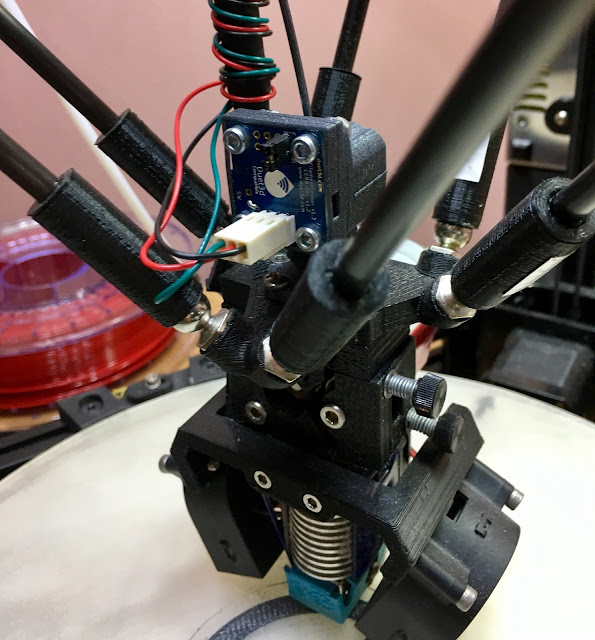
Here's the mount:

-
Do you have the second M591 D0 in config?
-
Calibration print is complete. I ran M591 8 times during the print and then when it was done. I got this everytime:
M591 D0
[[language]]
Duet3D filament sensor on endstop 4, no microswitch, 23.5mm per rev, check every 3.0mm, tolerance 50.0%, current angle 0.0
My 23.5mm/rev is exactly what the default setting was. I don't see a variation as mentioned in the Calibration section of the Wiki. I'll assume all is ok and get back to printing parts - now with a filament monitor watching over my prints.
-
I don't have M591 D0 in config. I added the entire M591 config line to config and then reloaded the file. I then ran M591 D-50 to go into calibration mode. Is this not correct?
-
Not according to the Wiki page. Need two lines.
Both lines. (in config.g)
Then M591 D0 C4 command.
Then M591 R-50 command.
Start print.
-
I thought the code in the Configuring Filament Monitoring box on the wiki were simply examples. The 591 D0 simply returns the string I pasted above so I don't see why that needs or should be in config.g. I seem to be functioning correctly. I am going to cut the filament and let it "run out" to see what happens.
-
All I can say is that is what the directions say. Even DJ had an issue.
-
IDK, it's working so I'll go with it. The directions don't explicitly say to add both commands, they simply say these are examples. Did you have an issue without the D0 line in the config?
-
Sorry, I am on the wrong side of the water to get these cool new gadgets.
I figure when DC writes "example" he just means that the variables of attachments to the Duet and such can be changed, as well as the rest of the M591. C, D and P needing to be defined. But having both of the lines written in the Wiki and the rest of the directions, are a must.
-
I have updated the calibration instructions to improve and clarify them.
-
David, in my M591 commands during the print the current angle always returned as "0.00". Does this imply that my sensor is actually not working properly and needs to be closer to the magnet?
-
My experience was that the angle should be read in when M591 D0 is sent.
Get the calibration data from m122 rather than from M591, then update the m591 settings. The unit does do what it is meant to.
-
Unless I'm missing something the wiki is still not correct, M122 reports the calibration information, M591 D0 just shows the settings from config plus the angle. Unless it behaves differently with 1.20 which I haven't installed yet, although am about to.
-
David, don't know if you saw my comment close to the top of this thread:
I'm in calibration mode and printing now. This is a part I print every day and my printer is acting very odd. It is printing and pausing every 6ish mm. Is this normal for calibration or is something wrong? I do see the LED flashing red. It is also not stuttering as much now as it was when I started writing but still obviously stuttering.
The problem continues. I disabled the M591 in config.g and behavior has returned to normal, albeit without the filament monitor operating. I suspect that my sensor is not reading the magnet but I'm not sure how to get it closer.
-
David, in my M591 commands during the print the current angle always returned as "0.00". Does this imply that my sensor is actually not working properly and needs to be closer to the magnet?
yes sounds like its not reading the magnet- you should get 3 or 4 gred and red together flashes at startup to show the magnet is registered properly
-
David, don't know if you saw my comment close to the top of this thread:
I'm in calibration mode and printing now. This is a part I print every day and my printer is acting very odd. It is printing and pausing every 6ish mm. Is this normal for calibration or is something wrong? I do see the LED flashing red. It is also not stuttering as much now as it was when I started writing but still obviously stuttering.
The problem continues. I disabled the M591 in config.g and behavior has returned to normal, albeit without the filament monitor operating. I suspect that my sensor is not reading the magnet but I'm not sure how to get it closer.
You are looking for a gap of~0.5mm this may be as simple in a variation between the printers we have printer the parts on. you can add a small shift in the SCAD or try just moving the hobb assembly very slightly where it is seated.
-
Thanks Tony, I'm taking it off and looking at it now.