SAMC21 ADC and voltage monitoring
-
@gixxerfast said in SAMC21 ADC and voltage monitoring:
By the way, what mechanism is hindering me from moving the motors if there is perceived overvoltage?
It's undervoltage that prevents the motors from moving, not overvoltage. Overvoltage detection is only used on the Duet 2 WiFi/Ethernet.
@gixxerfast said in SAMC21 ADC and voltage monitoring:
I don't have a clue what rail to rail means.
From the datasheet:
Enable rail-to-rail operation to increase the allowable range of the input common mode voltage
(VCMIN). When R2R is one, a sampling period of four cycles is required. Offset compensation
(SAMPCTRL.OFFCOMP) must be written to one when using this period.Duet WiFi hardware designer and firmware engineer
Please do not ask me for Duet support via PM or email, use the forum
http://www.escher3d.com, https://miscsolutions.wordpress.com -
@joergs5 Yes thanks, at this stage all ideas are good ideas.
")
-
@dc42 said in SAMC21 ADC and voltage monitoring:
It's undervoltage that prevents the motors from moving, not overvoltage. Overvoltage detection is only used on the Duet 2 WiFi/Ethernet.
Yes, that's what I thought. But when I enable voltage monitoring the stepper motors no longer works so I just wanted to check if I missed anything being reported back to the main board and thus hindering the commands.
When I meassure continuity and resistance between pin 6 on the MCU (VDDANA) and the V33 pin on the Sammy board I don't get direct continuity and the resistance is +500 kohms. The VDDANA is connected via an intermediate plane on the Sammy board at it seems to me that there's poor connection there somehow. That could explain it I guess.
-
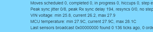
I couraged up and measured VDDANA on my Sammy and it is 2.46V
so 1.728V in with 2.46V ref voltage --> 32.1 V wich matches the output above.
Anyone can explain how a via connection to a power plane can disappear on a rail powered by a max 250mA 3.3V LDO ? Alla other input power pins (VDDIO and VDDIN) works.
I guess this Sammy will die as well whenever the VDDANA voltage goes under the min requirement.
As a note, my "dead" sammy woke up when I jumpered 3.3V to VDDANA. So it didn't die from ESD or shorting, it was only the VDDANA via that finally gave up. -
@dc42 said in SAMC21 ADC and voltage monitoring:
have you checked that the voltage on the VDDANA pin really is 3.3V?
This was really the problem. When I jumpered VDDANA directly from a known good 3.3V source instead of the via, even the formerly dead Sammy woke up and presented a correct result.
When later connected to the mini5+ and the voltage divider I get the correct result in the diagnostics. (My resistor values aren't entirely correct so there is a small diff)
Also the servo control jumped to life and works flawlessly (so far) which makes me draw some conclusions.
The Servo control is on pin PA04 and the voltage monitoring is on pin PA03 and they are accordning to the datasheet powered by VDDANA. The UART RX and TX is connected to PA20 and PA22 which are powered by VDDIO.
So if the Sammy's vias to the power plane are weak there might be a voltage drop in the UART signal that stops that from working correctly if I don't inject 3.3 to support the signal.Well that's an idea anyway and considering that I prior to this little project never worked with electronics it can very likely be wrong
Thanks for the tip about checking VDDANA.
-
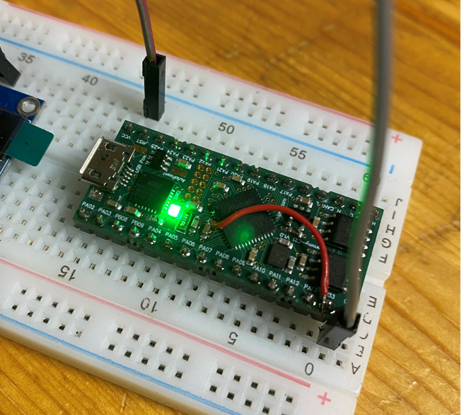
@gixxerfast to sum up you experience, what do you recommend when using Sammy-C21? Is it adding the red wire on the image and the resistor on the stepper driver which you showed in the other thread?
-
@joergs5 Hi, I can't recommend anything quite yet. The jumper should not be needed and I don't understand what has happened to the via/power plane. As with the pullup on the UART line, the same there really. I still don't understand why the Seeeduino XIAO with the SAMD18G and Klipper can handle the 20K pulldown on the UART/PDN but the SAMC18G/Sammy with RRF can't.
So, I really have more questions than answers at the moment.
I've just ordered a cheap logic analyzer so I hope to be able to see anything
But, as always with the "big" 100uF caps on the Vm connected to the drivers one should always be very carful when connecting/disconnecting.
-
@gixxerfast I understand. It would be nice if you can write some summary when you have "all your answers", to help development for others. There are lots of new possibilities connecting such boards like Sammy to the Duet.
-
@joergs5 Sure will
@dc42 If you have a minute to spare.
The (jumpered) Sammy-board is now working with the VIN-monitoring, servo control and UART-controlled drivers with the Sammy firmware.However, now, after all this, the UART control only works if I remove the 20K pulldown from the step sticks and add a 20K pullup on the RX (or TX). I wasn't successful with the 4.7K together with the pulldown any longer. I don't know why.
As I know for a fact that the Seeeduino works with stock step sticks with the pull down and no external pullup I had to dig into the Klipper code and I just barely understand what I'm reading but this is what I'm thinking.
The Duet3 boards (mini5+ and 1LC) all have an external 27K or 22K pullup and the TMC2209 directly on the board.
When I read the TMC2209 datasheet I see that the UART line must be kept high during idle.
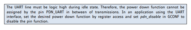
Which I guess you do using the external pullup, since I can't measure a high idle signal (with my crude multimeter). (Or now when I read it again, do you set pdn_disable?)In the Klipper code I find this (which I right now haven't been able to follow completely)
void
command_config_tmcuart(uint32_t *args)
{
    struct tmcuart_s *t = oid_alloc(args[0], command_config_tmcuart
                                    , sizeof(*t));
    uint8_t pull_up = args[2];
    uint32_t rx_pin = args[1], tx_pin = args[3];
    t->rx_pin = gpio_in_setup(rx_pin, !!pull_up);
    t->tx_pin = gpio_out_setup(tx_pin, 1);
    t->cfg_bit_time = args[4];
    t->flags = (TU_LINE_HIGH | (pull_up ? TU_PULLUP : 0)
                | (rx_pin == tx_pin ? TU_SINGLE_WIRE : 0));
}
DECL_COMMAND(command_config_tmcuart,
             "config_tmcuart oid=%c rx_pin=%u pull_up=%c"
             " tx_pin=%u bit_time=%u");
My interpretation of this is that it configures UART to have line high (during idle), enable internal pullup on TX and have an optional possibility of the same on the RX.
So my question is can I do the same in the Duet firmware?
Maybe it's already done but I'm totally lost following the Sercom configuration code right now. I have not been able to measure it yet though.
-
@gixxerfast the internal pullup resistors in the SAM processors have a value of around 100K which is too weak to overcome the 20K resistors on the stepsticks. However, once the UART transmitter has been enabled, that should be enough to defeat the pullup resistors. My assumption was that the reason for the problem you encountered was that the TMC chips read the state of the PDN/UART pin at power up, before the UART is initialised.
Duet WiFi hardware designer and firmware engineer
Please do not ask me for Duet support via PM or email, use the forum
http://www.escher3d.com, https://miscsolutions.wordpress.com -
@dc42 OK, but then I still have that problem since now I can't get the TMCs connected even with a 4.7K pullup.
EDIT 2: Aha, know I understand what you mean. But that problem should be with any board without pullups. Wouldn't an idle high line fix this though. so the pdn pin goes high before the Sercom/UART start chatting?
(IDK, something changed with the VDDANA back to level. I have been reconfiguring recompiling and swapping step stick like a maniac with and without external pullups, but in the end the only thing that get to work is 20K external pullup and removed pulldown on the step sticks.)
Edit. Never mind the question below. Found it:
constexpr uint32_t GCONF_UART = 1 << 6; // PDN_UART used for UART interface (else used for power down)But with the idle UART line high, should I not be able to measure 3.3V (ish) or do you use the pdn_disable as described above? -
@gixxerfast maybe it's something simple like needing to add a delay between initialising the UART (so that the TxD output is high) and the first communication with the TMC2209.