Duet3D Logo Duet3D
    • Tags
    • Documentation
    • Order
    • Register
    • Login

    Printing problem duet fw config bad or Siemens drivers bad

    Scheduled Pinned Locked Moved
    Firmware installation
    3
    18
    561
    Loading More Posts
    • Oldest to Newest
    • Newest to Oldest
    • Most Votes
    Reply
    • Reply as topic
    Log in to reply
    This topic has been deleted. Only users with topic management privileges can see it.
    • createc3dundefined
      createc3d
      last edited by

      Hello,
      we already have a working big 3D printer with Duet 3 6HC and Nema 23 stepper motors, all with their external drivers boards Duet 3 expansion board 1 XD, now it's working fine with no problems.

      We assembled other machine but with Siemens servo motors (1FL6032-2AF21-1AA1) and servo drives (6SL3210-5FB10-2UA2) that works by pulse, but the result of the printing is this:

      badprinting.jpg

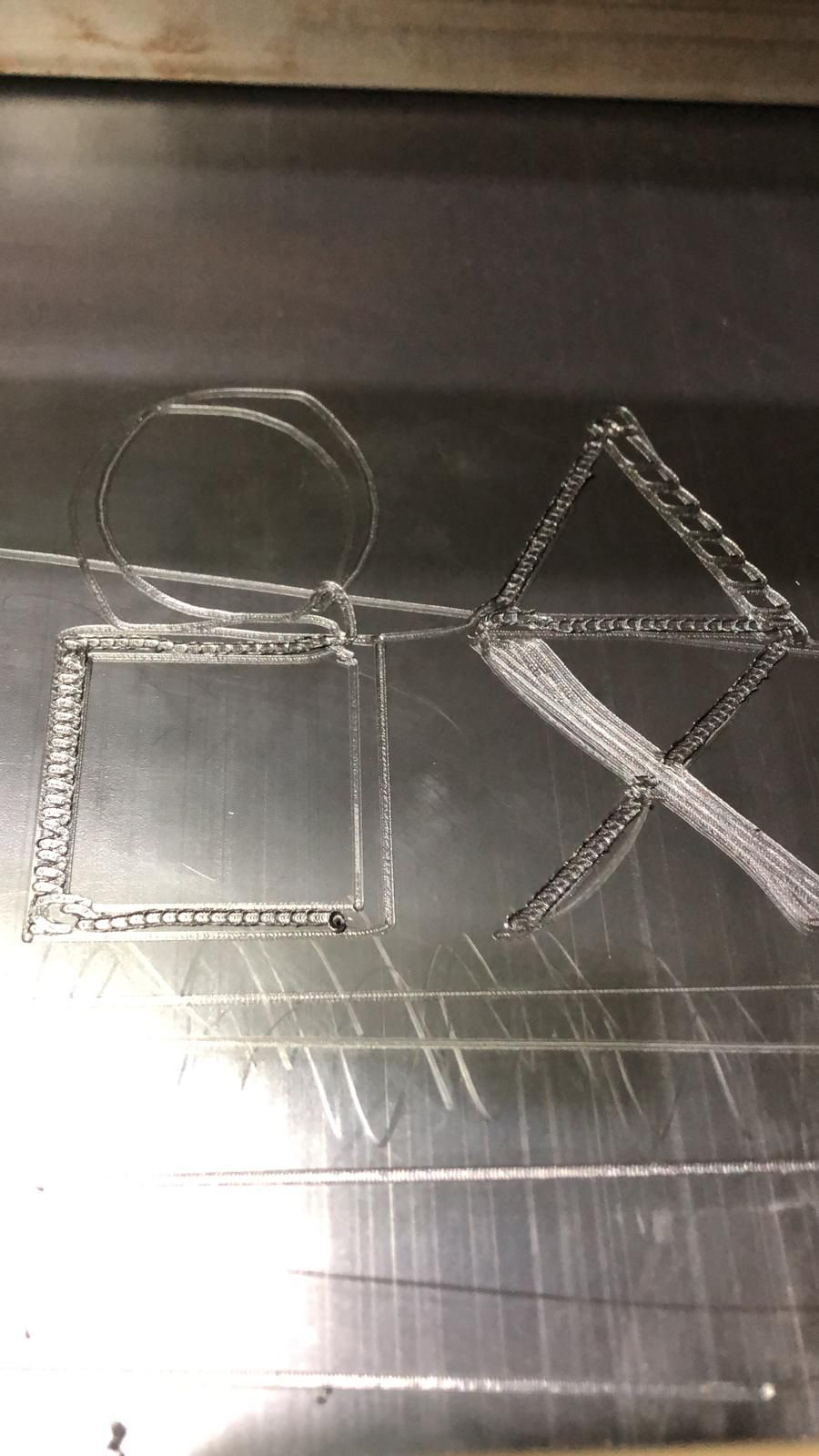
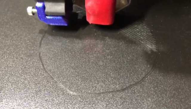
      Circles are not circles... in one direction seems to print fine but in others not... see the triangle figure for example... or X...

      The Gcode is made with Simplify like in all our machines.

      We have the firmware of duet config tested on normal steppers and works good so we think the problem is the configuration of Servo Drives of Siemens, but people of Siemens said that problem is on Duet board configuration.

      Any ideas?

      Thank you.

      jay_s_ukundefined dc42undefined 2 Replies Last reply Reply Quote 0
      • jay_s_ukundefined
        jay_s_uk @createc3d
        last edited by

        @createc3d post your config

        Owns various duet boards and is the main wiki maintainer for the Teamgloomy LPC/STM32 port of RRF. Assume I'm running whatever the latest beta/stable build is

        1 Reply Last reply Reply Quote 0
        • dc42undefined
          dc42 administrators @createc3d
          last edited by

          @createc3d it may be that the drivers need slower timings than the default ones provided by the 1XD boards. Please post a link to the datasheet for those drivers, along with your config.g file.

          Duet WiFi hardware designer and firmware engineer
          Please do not ask me for Duet support via PM or email, use the forum
          http://www.escher3d.com, https://miscsolutions.wordpress.com

          createc3dundefined 1 Reply Last reply Reply Quote 0
          • createc3dundefined
            createc3d @dc42
            last edited by

            @dc42 the drivers are this:
            https://support.industry.siemens.com/cs/dl-media/109793552/142040542347_en-US/start.htm?lc=en

            and the config file is:

            ; Configuration file for Duet 3 (firmware version 3.3)
            ; executed by the firmware on start-up
            ;
            ; generated by RepRapFirmware Configuration Tool v3.3.10 on Thu Feb 24 2022 09:21:45 GMT+0100 (hora estándar de Europa central)
            
            
            ; General preferences
            G90                                                ; send absolute coordinates...
            M83                                                ; ...but relative extruder moves
            M550 P"Atarfil"                                    ; set printer name
            
            M575 P1 S1 B57600
            
            ; Wait a moment for the CAN expansion boards to start
            G4 S2
            
            ; Network
            M552 P0.0.0.0 S1                                   ; enable network and acquire dynamic address via DHCP
            M586 P0 S1                                         ; enable HTTP
            M586 P1 S0                                         ; disable FTP
            M586 P2 S0                                         ; disable Telnet
            
            ; Drives
            M569 P40 	S0    	R0 T2.7                               	   ; physical drive 121.0 goes forwards
            M569 P41.0 	S1  	R0 T2.7                                    ; physical drive 122.0 goes forwards
            M569 P42.0 	S1	 	R0 T2.7                                    ; physical drive 123.0 goes forwards
            M569 P43.0 	S1	    R0 T2.7 				 				   ; physical drive 124.0 goes forwards
            M569 P0 S0  		R0  				                       ; R0 MODIFICACION 
            	                                   
            M584 X40.0 
            M584 Y41.0 
            M584 Z42.0
            M584 Z43.0 
             
            M584 E0                                            ; set drive mapping
            M350 X11.11 Y6.25 Z10 E16 I1                               ; configure microstepping with interpolation
            M92 X11.11 Y6.15 Z200  E600                  		   ; set steps per mm
            M566 X900.00 Y900.00 Z60.00 E120.00                ; set maximum instantaneous speed changes (mm/min)
            M203 X6000.00 Y6000.00 Z100.00 E1200.00            ; set maximum speeds (mm/min)
            M201 X500.00 Y500.00 Z10.00 E250.00                ; set accelerations (mm/s^2)
            M906 X800 Y800 Z800 E1680 I30                       ; set motor currents (mA) and motor idle factor in per cent
            M84 S30                                            ; Set idle timeout
            
            ; Axis Limits
            M208 X0 Y0 Z0 S1                                   ; set axis minima
            M208 X2200 Y200 Z70 S0                            ; set axis maxima
            
            ; Endstops
            M574 X1 S1 P"io1.in"                           ; configure switch-type (e.g. microswitch) endstop for low end on X via pin 121.io0.in
            M574 Y1 S1 P"io2.in"                           ; configure switch-type (e.g. microswitch) endstop for low end on Y via pin 122.io0.in
            M574 Z1 S1 P"io3.in+io4.in"                           ; configure switch-type (e.g. microswitch) endstop for low end on Z via pin 123.io0.in
                                       ; configure switch-type (e.g. microswitch) endstop for low end on Z via pin 123.io0.in
            
            ; Z-Probe
            M558 P0 H5 F120 T6000                              ; disable Z probe but set dive height, probe speed and travel speed
            M557 X15:215 Y15:195 S20                           ; define mesh grid
            
            ; Heaters
            
            M308 S0 P"temp3" Y"thermistor" T100000 B4138  ; configure sensor 0 as thermistor on pin bedtemp
            M950 H0 C"out0" T0                           ; create bed heater output on bedheat and map it to sensor 0
            M307 H0 A340 C2745.9 D25 S1.00 B0                               ; enable bang-bang mode for the bed heater and set PWM limit
            M140 H0                                         ; map heated bed to heater 0
            M143 H0 S120                                    ; set temperature limit for heater 0 to 120C
            M308 S1 P"temp0" Y"thermistor" T100000 B4138   ; configure sensor 1 as thermistor on pin e0temp
            M950 H1 C"out1" T1                            ; create nozzle heater output on e0heat and map it to sensor 1
             M307 H1 B0 R1.278 C282.5 D6.68 S1.00 V23.1                             ; disable bang-bang mode for heater  and set PWM limit
            M143 H1 S280  
            
            ; Fans
            M950 F0 C"out5" Q500                               ; create fan 0 on pin out4 and set its frequency
            M106 P0 S0 H-1                                     ; set fan 0 value. Thermostatic control is turned off
            M950 F1 C"out4" Q500                               ; create fan 1 on pin out5 and set its frequency
            M106 P1 S1 H1 T45                                  ; set fan 1 value. Thermostatic control is turned on
            
            ; Tools
            ;M563 P0 S”v4” D0 H1 ; Define tool 0
            M563 P0 D0 H1 F0                                   ; define tool 0
            G10 P0 X0 Y0 Z0                                    ; set tool 0 axis offsets
            G10 P0 R0 S0                                       ; set initial tool 0 active and standby temperatures to 0C
            
            ; Custom settings are not defined
            
            ; Miscellaneous
            M911 S10 R11 P"M913 X0 Y0 G91 M83 G1 Z3 E-5 F1000" ; set voltage thresholds and actions to run on power loss


            dc42undefined 1 Reply Last reply Reply Quote 0
            • dc42undefined
              dc42 administrators @createc3d
              last edited by dc42

              @createc3d I was unable to find the parameters required in the document you linked to. The parameters needed are:

              Minimum step pulse width
              Minimum step pulse interval
              Required setup time from change in direction signal to leading edge of step pulse
              Required hold time from trailing edge of step pulse to change in direction signal

              Currently you have set all of these to 2.7 microseconds. I suspect that at least one of them needs to be increased.

              Please upgrade to firmware 3.4.0 if you are not already using it.

              Duet WiFi hardware designer and firmware engineer
              Please do not ask me for Duet support via PM or email, use the forum
              http://www.escher3d.com, https://miscsolutions.wordpress.com

              createc3dundefined 1 Reply Last reply Reply Quote 0
              • createc3dundefined
                createc3d @dc42
                last edited by

                @dc42 I asked Siemens about the data needed and the only thing they can say is this:

                They use RS 485 to receive pulses at a máximum frecuency of 1MHz...

                They don't tell us anything about "ms" or anything else.

                We may increase randomly to see if it works fine?

                dc42undefined 1 Reply Last reply Reply Quote 0
                • dc42undefined
                  dc42 administrators @createc3d
                  last edited by

                  @createc3d in your M569 commands I suggest you try this T parameter:

                  T2.5:2.5:5:5

                  If that works, try reducing the last value to zero. It's usually the third value that needs to be increased when there are issues with direction changes.

                  Duet WiFi hardware designer and firmware engineer
                  Please do not ask me for Duet support via PM or email, use the forum
                  http://www.escher3d.com, https://miscsolutions.wordpress.com

                  createc3dundefined 2 Replies Last reply Reply Quote 0
                  • createc3dundefined
                    createc3d @dc42
                    last edited by

                    @dc42 Ok, we'll try next week and let you know, because the machine is in other company and can't go to check today.

                    Thank you.

                    1 Reply Last reply Reply Quote 0
                    • createc3dundefined
                      createc3d @dc42
                      last edited by

                      @dc42 hello, we've been testing and it's a bit better but still it's not good.

                      We tried with T2.5:2.5:5:5 but it was not better.

                      Then with T2.5:2.5:5:0 was a little improvement.

                      Then we tried increasing the third value to 10, 20... up to 100 but no change, same results.

                      We also tried without the T parameter and values and the results was the same that T2.5:2.5:5:0.

                      Captura 2022-04-11 a las 10.28.05.png

                      Can we try anything else?

                      jay_s_ukundefined 1 Reply Last reply Reply Quote 0
                      • jay_s_ukundefined
                        jay_s_uk @createc3d
                        last edited by

                        @createc3d try T5:5:10:10

                        Owns various duet boards and is the main wiki maintainer for the Teamgloomy LPC/STM32 port of RRF. Assume I'm running whatever the latest beta/stable build is

                        createc3dundefined 1 Reply Last reply Reply Quote 1
                        • createc3dundefined
                          createc3d @jay_s_uk
                          last edited by

                          @jay_s_uk Hello, still is not doing it right

                          Captura 2022-04-12 a las 9.34.15.png

                          dc42undefined 1 Reply Last reply Reply Quote 0
                          • dc42undefined
                            dc42 administrators @createc3d
                            last edited by

                            @createc3d if you send M569 P41.0 and similarly for the CAN addresses of the other 1XD boards, does it report the correct T values that you used? Some of them will be rounded up to the next multiple of 1.33us.

                            If you send M98 P"config.g" are there any error messages?

                            Duet WiFi hardware designer and firmware engineer
                            Please do not ask me for Duet support via PM or email, use the forum
                            http://www.escher3d.com, https://miscsolutions.wordpress.com

                            dc42undefined createc3dundefined 2 Replies Last reply Reply Quote 0
                            • dc42undefined
                              dc42 administrators @dc42
                              last edited by

                              PS have you checked for loose pulleys etc.? That pattern of a straight line segment appearing in what should be a circle is characteristic of a large amount of backlash.

                              Duet WiFi hardware designer and firmware engineer
                              Please do not ask me for Duet support via PM or email, use the forum
                              http://www.escher3d.com, https://miscsolutions.wordpress.com

                              createc3dundefined 1 Reply Last reply Reply Quote 1
                              • createc3dundefined
                                createc3d @dc42
                                last edited by

                                @dc42 Hello, sorry for delay, here with easter week we didn't have the possibility to go to the place where the machine is installed until today.

                                This is the result of M98 P"config.g"
                                ERRORCODES.jpg

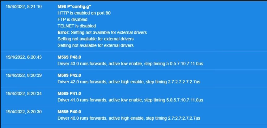
                                P40 and P41 are X and Y axis, P42 is not in use at the moment and P43 is Z axis.

                                And config file is now:

                                ; Configuration file for Duet 3 (firmware version 3.3)
                                ; executed by the firmware on start-up
                                ;
                                ; generated by RepRapFirmware Configuration Tool v3.3.10 on Thu Feb 24 2022 09:21:45 GMT+0100 (hora estándar de Europa central)
                                
                                
                                ; General preferences
                                G90                                                ; send absolute coordinates...
                                M83                                                ; ...but relative extruder moves
                                M550 P"Atarfil"                                    ; set printer name
                                
                                M575 P1 S1 B57600
                                
                                ; Wait a moment for the CAN expansion boards to start
                                G4 S2
                                
                                ; Network
                                M552 P0.0.0.0 S1                                   ; enable network and acquire dynamic address via DHCP
                                M586 P0 S1                                         ; enable HTTP
                                M586 P1 S0                                         ; disable FTP
                                M586 P2 S0                                         ; disable Telnet
                                
                                ; Drives
                                M569 P40.0 	S0    	R0 T5:5:10:10                               	   ; physical drive 121.0 goes forwards
                                M569 P41.0 	S1  	R0 T5:5:10:10                                  ; physical drive 122.0 goes forwards
                                M569 P42.0 	S1	 	R0 T5:5:10:10                                   ; physical drive 123.0 goes forwards
                                M569 P43.0 	S1	    R0 T5:5:10:10 				 				   ; physical drive 124.0 goes forwards
                                M569 P0 S0  		R0  				                       ; R0 MODIFICACION 
                                	                                   
                                M584 X40.0 
                                M584 Y41.0 
                                M584 Z42.0
                                M584 Z43.0 
                                 
                                M584 E0                                            ; set drive mapping
                                M350 X11.11 Y6.25 Z10 E16 I1                               ; configure microstepping with interpolation
                                M92 X11.11 Y6.15 Z200  E600                  		   ; set steps per mm
                                M566 X900.00 Y900.00 Z60.00 E120.00                ; set maximum instantaneous speed changes (mm/min)
                                M203 X6000.00 Y6000.00 Z100.00 E1200.00            ; set maximum speeds (mm/min)
                                M201 X500.00 Y500.00 Z10.00 E250.00                ; set accelerations (mm/s^2)
                                M906 X800 Y800 Z800 E1680 I30                       ; set motor currents (mA) and motor idle factor in per cent
                                M84 S30                                            ; Set idle timeout
                                
                                ; Axis Limits
                                M208 X0 Y0 Z0 S1                                   ; set axis minima
                                M208 X2200 Y200 Z70 S0                            ; set axis maxima
                                
                                ; Endstops
                                M574 X1 S1 P"io1.in"                           ; configure switch-type (e.g. microswitch) endstop for low end on X via pin 121.io0.in
                                M574 Y1 S1 P"io2.in"                           ; configure switch-type (e.g. microswitch) endstop for low end on Y via pin 122.io0.in
                                M574 Z1 S1 P"io3.in+io4.in"                           ; configure switch-type (e.g. microswitch) endstop for low end on Z via pin 123.io0.in
                                                           ; configure switch-type (e.g. microswitch) endstop for low end on Z via pin 123.io0.in
                                
                                ; Z-Probe
                                M558 P0 H5 F120 T6000                              ; disable Z probe but set dive height, probe speed and travel speed
                                M557 X15:215 Y15:195 S20                           ; define mesh grid
                                
                                ; Heaters
                                
                                M308 S0 P"temp3" Y"thermistor" T100000 B4138  ; configure sensor 0 as thermistor on pin bedtemp
                                M950 H0 C"out0" T0                           ; create bed heater output on bedheat and map it to sensor 0
                                M307 H0 A340 C2745.9 D25 S1.00 B0                               ; enable bang-bang mode for the bed heater and set PWM limit
                                M140 H0                                         ; map heated bed to heater 0
                                M143 H0 S120                                    ; set temperature limit for heater 0 to 120C
                                M308 S1 P"temp0" Y"thermistor" T100000 B4138   ; configure sensor 1 as thermistor on pin e0temp
                                M950 H1 C"out1" T1                            ; create nozzle heater output on e0heat and map it to sensor 1
                                 M307 H1 B0 R1.278 C282.5 D6.68 S1.00 V23.1                             ; disable bang-bang mode for heater  and set PWM limit
                                M143 H1 S280  
                                
                                ; Fans
                                M950 F0 C"out5" Q500                               ; create fan 0 on pin out4 and set its frequency
                                M106 P0 S0 H-1                                     ; set fan 0 value. Thermostatic control is turned off
                                M950 F1 C"out4" Q500                               ; create fan 1 on pin out5 and set its frequency
                                M106 P1 S1 H1 T45                                  ; set fan 1 value. Thermostatic control is turned on
                                
                                ; Tools
                                ;M563 P0 S”v4” D0 H1 ; Define tool 0
                                M563 P0 D0 H1 F0                                   ; define tool 0
                                G10 P0 X0 Y0 Z0                                    ; set tool 0 axis offsets
                                G10 P0 R0 S0                                       ; set initial tool 0 active and standby temperatures to 0C
                                
                                ; Custom settings are not defined
                                
                                ; Miscellaneous
                                M911 S10 R11 P"M913 X0 Y0 G91 M83 G1 Z3 E-5 F1000" ; set voltage thresholds and actions to run on power loss


                                1 Reply Last reply Reply Quote 0
                                • createc3dundefined
                                  createc3d @dc42
                                  last edited by

                                  @dc42 we have a person now checking all mechanics in case there's some problem with it also.

                                  dc42undefined 1 Reply Last reply Reply Quote 0
                                  • dc42undefined
                                    dc42 administrators @createc3d
                                    last edited by

                                    @createc3d another test you can do is to approach a particular point (say X=100) from one direction (e.g. from X50) and then from the other (e.g. X150) and check whether the print head goes to exactly the same place in both cases.

                                    Duet WiFi hardware designer and firmware engineer
                                    Please do not ask me for Duet support via PM or email, use the forum
                                    http://www.escher3d.com, https://miscsolutions.wordpress.com

                                    createc3dundefined 2 Replies Last reply Reply Quote 0
                                    • createc3dundefined
                                      createc3d @dc42
                                      last edited by

                                      @dc42 I'm going to tell the people with the machine to do this test, but I think in linear movement the machine has no problem.

                                      About the information before, why is different the step timming in the drivers if we have in config.g the same for all of them?

                                      1 Reply Last reply Reply Quote 0
                                      • createc3dundefined
                                        createc3d @dc42
                                        last edited by

                                        @dc42 this test was fine... but we tried to print two lines, one with 45 degrees and other with 3 degrees... the 45º line was drawn ok, but the 3º line the machine only moves in X axis... the Y was not moving... any ideas?

                                        1 Reply Last reply Reply Quote 0
                                        • First post
                                          Last post
                                        Unless otherwise noted, all forum content is licensed under CC-BY-SA