Duet3D Logo Duet3D
    • Tags
    • Documentation
    • Order
    • Register
    • Login
    1. Home
    2. jay_s_uk
    • Profile
    • Following 1
    • Followers 24
    • Topics 126
    • Posts 7,050
    • Best 1,344
    • Controversial 7
    • Groups 1

    jay_s_uk

    @jay_s_uk

    1.6k
    Reputation
    709
    Profile views
    7.0k
    Posts
    24
    Followers
    1
    Following
    Joined Last Online
    Website www.jayuk.org Location Darlington Age 40

    jay_s_uk Unfollow Follow
    Moderator

    Best posts made by jay_s_uk

    • Pattern Pressure Advance Calibration

      For the last few weeks, there has been a new method of calibrating pressure advance with klipper called the pattern method. This is now the recommended method to use over the lines method.

      As of a few minutes ago, the online generator now has RRF support too.

      The pattern PA calibration generator can be found here https://ellis3dp.com/Pressure_Linear_Advance_Tool/ and the information about how to interpret it can be found here https://ellis3dp.com/Print-Tuning-Guide/articles/pressure_linear_advance/introduction.html

      posted in Tuning and tweaking
      jay_s_ukundefined
      jay_s_uk
    • LDO BoxTurtle V1.0 RRF Support

      I am pleased to announce provisional support for the LDO BoxTurtle V1.0 with RepRapFirmware.
      This setup uses the stock AFC-Lite board which comes in the kit. Wiring is as per the stock BoxTurtle Instructions.

      The macros can be found here https://github.com/jaysuk/BoxTurtle_RRF
      Instructions for getting the AFC-Lite flashed can be found here https://teamgloomy.github.io/afc_lite_v1_0_h723_general_3_5.html

      This setup will work with any of the Duet 3 mainboards (i.e. 6HC, 6XD, mini 5+), and any of the STM32H7 mainboards. I'm not sure it will be possible with an STM32F4 based board with spi2can module purely because of the amount of globals used.

      Features currently implemented
      So far this has the following features implemented:

      Brush - tested
      Cut - tested
      Kick - untested
      Poop - untested
      Purge - tests
      filament runout - untested
      It is highly recommended to run this with a cutter on your printer as there is currently no tip forming enabled.
      This also only works with one AFC. Connecting multiple AFC's is currently not supported.

      Brushing Notes
      It is assumed that the macros will have full control of deploying and retracting the brush (if its servo based).
      If you already have the brush setup, create two macros in the AFC folder called "brush_deploy.g" and "brush_retract.g" and include in them the commands required to deploy and retract your brush.

      How to use
      Ensure the AFC is flashed with the correct version of RRF and connect it to your printer (only works with 3.6.0-RC1 onwards). Copy all the files to your sys and macros folders.
      Add the following to the very end of your config.g.

      G4 S2
      
      M98 P"0:/sys/AFC/AFC.g"
      

      Reboot your printer.
      Run the macro "Create System Files" and select all. Load some filemant to each lane. Run the macro "Lane - Measure First" for each lane. Run the macro "Measure Main Length" choosing one of the lanes to use. It doesn't matter which.

      Rename the file "AFC_user_vars_example.g" in the AFC folder to "AFC_user_vars.g" and edit each of the variables to suit your machine.
      Remember to enable the features you want to use.

      Reboot your machine and you should be good to go.

      I have also included a print_start.g file and a stop.g file. These should be suitable for using with your machine.

      Slicer Setup
      Orcaslicer is the recommended slicer to use.

      Setup your slicer as per the instructions here https://github.com/ArmoredTurtle/BoxTurtle/blob/main/Initial_Startup.md#configuring-your-slicer.

      Add the following to the machine start gcode

      M104 S0 ; Stops OrcaSlicer from sending temperature waits separately
      M140 S0 ; Stops OrcaSlicer from sending temperature waits separately
      M98 P"start_print.g" A{first_layer_bed_temperature[0]} B"{filament_type[0]}" C{first_layer_temperature[0]} D{nozzle_diameter[0]} E{first_layer_print_min[0]} F{first_layer_print_max[0]} H{first_layer_print_min[1]} J{first_layer_print_max[1]} K{initial_tool}
      

      To the change filament g-code add the following

      M98 P"0:/sys/AFC/set_temp_global.g" A[next_extruder] B[new_filament_temp]
      T[next_extruder]
      

      BtnCmd
      I have also included a basic BtnCmd setup for the AFC that I will be improving when I get time.

      Please post here or come find me on the RRF discord channel if you need support

      posted in Accessories and Add-ons
      jay_s_ukundefined
      jay_s_uk
    • RRF Compatible Stealthburner CAN-FD board finally released

      I am pleased to announce that RRF finally has a compatible Stealthburner CAN-FD board. https://s.click.aliexpress.com/e/_DdqyPGN
      There are two versions that are compatible with RRF (and as a bonus are also compatible with klipper), the SB2040 Max v3 and the SB2040 Pro Max v3.

      The SB2040 Max v3 has the following main features

      • TMC2209 driver

      • LIS2DW onboard accelerometer

      • Onboard LC1612 for Z Scanning Probe support. This is the same as the Duet3D SZP. It is also compatible with Duet3D scanning probe heads.

      • MAX31865 onboard for PT100 support.

      The SB2040 Pro Max v3 swaps the TMC2209 for a TMC2240.

      Documentation will be on the teamgloomy wiki in the coming days.

      posted in RepRapFirmware on other controllers
      jay_s_ukundefined
      jay_s_uk
    • STM32H7 Port of RRF 3.4.1RC1 - with CAN-FD support

      @gloomyandy and TeamGloomy are pleased to announce the initial release of the STM32H7 port of RRF (reprapfirmware). This build is based on RRF 3.4.1-RC1.
      What does this bring over the STM32F4 port?
      • A more powerful processor (480MHz compared to 300MHz of a Duet 3 6HC) with lots of spare flash and ram
      • More hardware SPI channels
      • Proper cache which helps with performance
      • Better floating point support (double precision)
      • 16bit ADC compared to 12bits on the STM32F4 (14bits with oversampling)
      • CAN-FD Support with full support for the RRF CAN-FD protocol including all available expansion boards (e.g. 1LC Toolboard)
      Some of the above hardware advantages of the STM32H7 aren’t currently used (such as hardware double precision for the 16bit ADC) but they are on the implementation list.
      Does this mean we will be dropping STM32F4 support?
      No! The STM32F4 builds are built from the same source as the STM32H7 builds. The STM32F4 builds will continue to have support for as long as the Duet 3 Mini has support (and maybe even longer).
      What boards can I run this on?
      There are currently 3 boards that can run the STM32H7 port of RRF. They are:
      • Fly-Super5
      • Bigtreetech SKR3 - https://www.aliexpress.com/item/1005004291817213.html
      • Bigtreetech SKR3 EZ - https://www.aliexpress.com/item/1005004295073346.html
      Where can I get this?
      The source and pre-compiled versions can be found here https://github.com/gloomyandy/RepRapFirmware and documentation can be found here https://teamgloomy.github.io/

      posted in STM
      jay_s_ukundefined
      jay_s_uk
    • Are your drivers outputting the current expected?

      After recently making some changes to one of my printers, I was running into issues with layer shifting etc and I wanted to investigate further. I was lucky enough to be able to purchase one of @zapta fantastic stepper motor analysers and I thought now was the perfect time to put it to good use.

      For reference, the machine in question has a Fly-E3-Pro installed (which has onboard 2209 drivers) utilising the STM32 port of RRF (3.4.1_102) and uses E3D high torque motors (1680 max peak, set to 1344ma in the firmware).

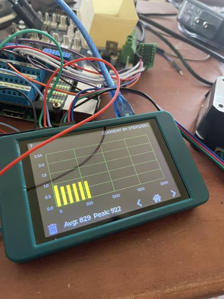
      Here is a photograph of the readings taken using the stepper motor analyser.
      PXL_20220628_080155173.jpg
      As you can see, the readings (which are in peak on the stepper motor analyser), aren't the values that I was expecting.

      I ran a few more tests using the same board, setting different currents and was getting similar readings. I then switched to a Fly-E3 board I had on the bench, along with a Fly-2209 driver and was getting similar results as the Fly-E3-Pro.

      I also tested a TMC5160 and that performed as expected so I have discounted the 5160 drivers from any further testing.

      Discussions were then had with @gloomyandy to ensure that the STM32 port of RRF was calculating the current both as per the trinamic datasheet (pg 53 of https://www.trinamic.com/fileadmin/assets/Products/ICs_Documents/TMC2209_datasheet_rev1.08.pdf) and in the same manner as the Duet version of RRF. It was confirmed it was, which prompted the need for wider testing to be carried out using both a Duet 3 Mini 5+ and an array of different drivers and boards running RRF, Klipper and Marlin.

      It may have been apparent with the previous screenshot of the stepper motor analyser, that unfortunately, the current is output on a histogram rather than some actual values (yes, there are other screens but the none of them actually show the peak value and are merely real-time values). Luckily for me @Sindarius not only was willing to mod the firmware to display a reading on that screen, he also had a stepper motor analyser to hand for testing those changes. Without @Sindarius help, the testing below would not have been possible so a big shout out to him!

      2e62a436-ecbf-48d2-92d1-a3bab40571af-image.png

      I gathered a collection of boards and tested an E3D high torque stepper (under no load conditions) to each of them in turn, adjusting the M906 requested current value. They all used the same config (x16 micro stepping and no interpolation) and the results can be seen below.

      7ec92c57-a994-4c6c-9865-59c59db584eb-image.png

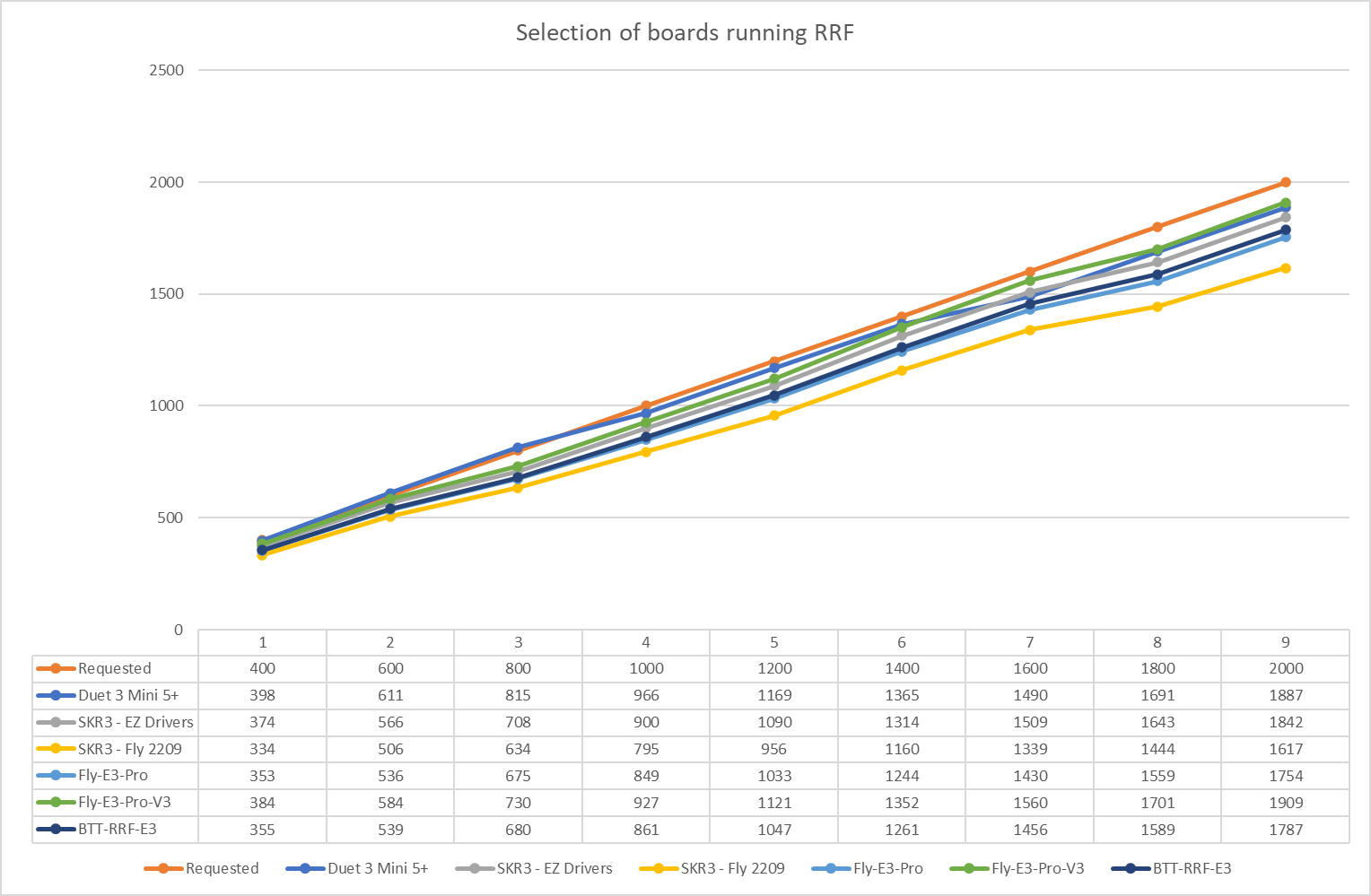
      A can be seen, the Duet 3 mini 5+ performed consistently well up to 1400mA, with a little bit of current drop off above that. The Fly-E3-Pro-V3 also performed consistently well. The EZ 2209 drivers performed worst at 800mA where the output current was 12.2% lower than the requested current. The Fly 2209 ran consistently ~18-22% lower than the current requested and were the worst performing on the chart. Both the Fly-E3-Pro and BTT-RRF-E3 ran around 10-15% lower than requested.

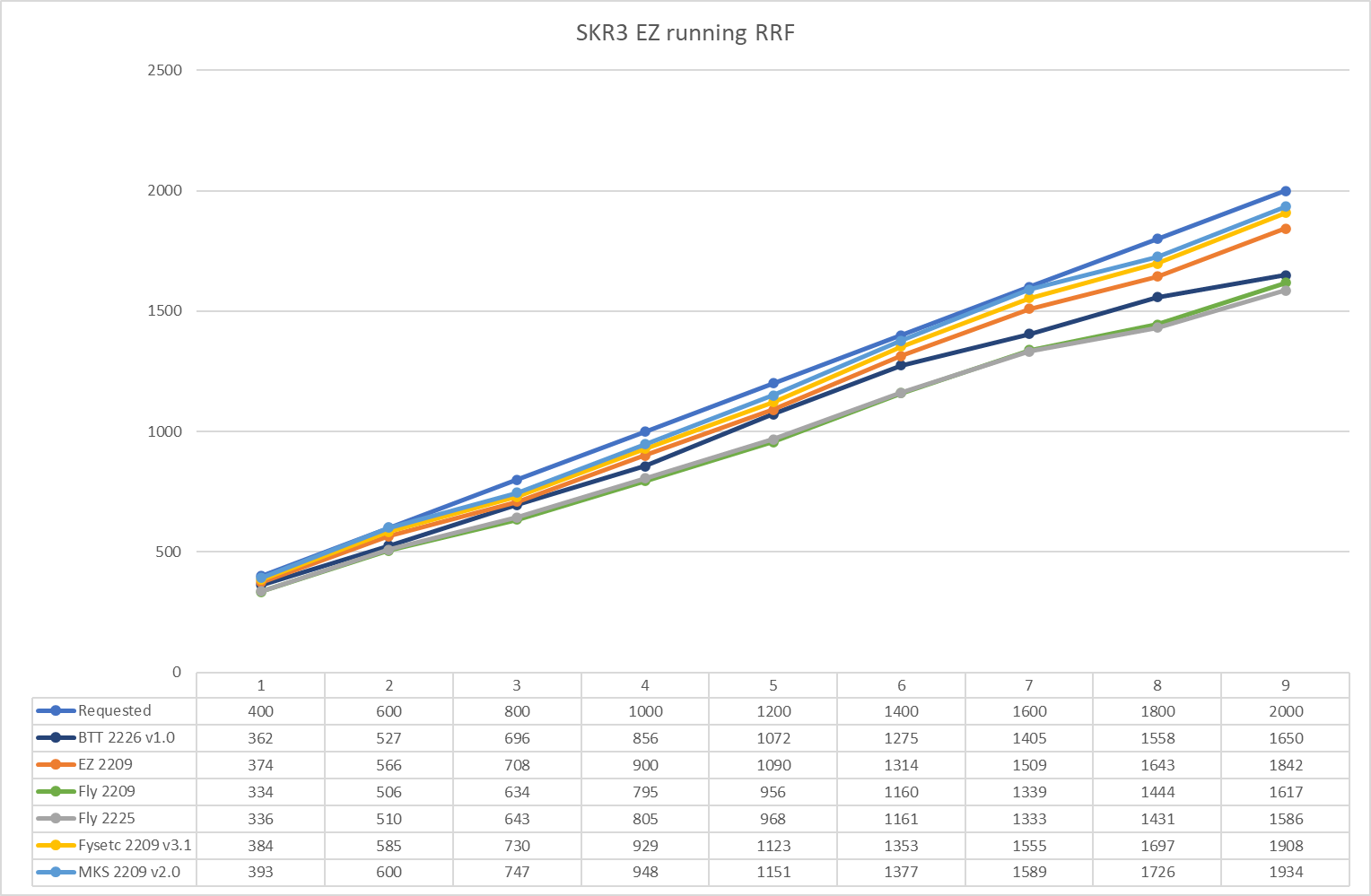
      I then ran the same current tests using an SKR3 EZ board. First running RRF

      5b94491b-47bf-41da-897f-94cec1ec664f-image.png

      and then running Klipper

      a7ea21a5-9f97-439b-abee-12f269daaea6-image.png

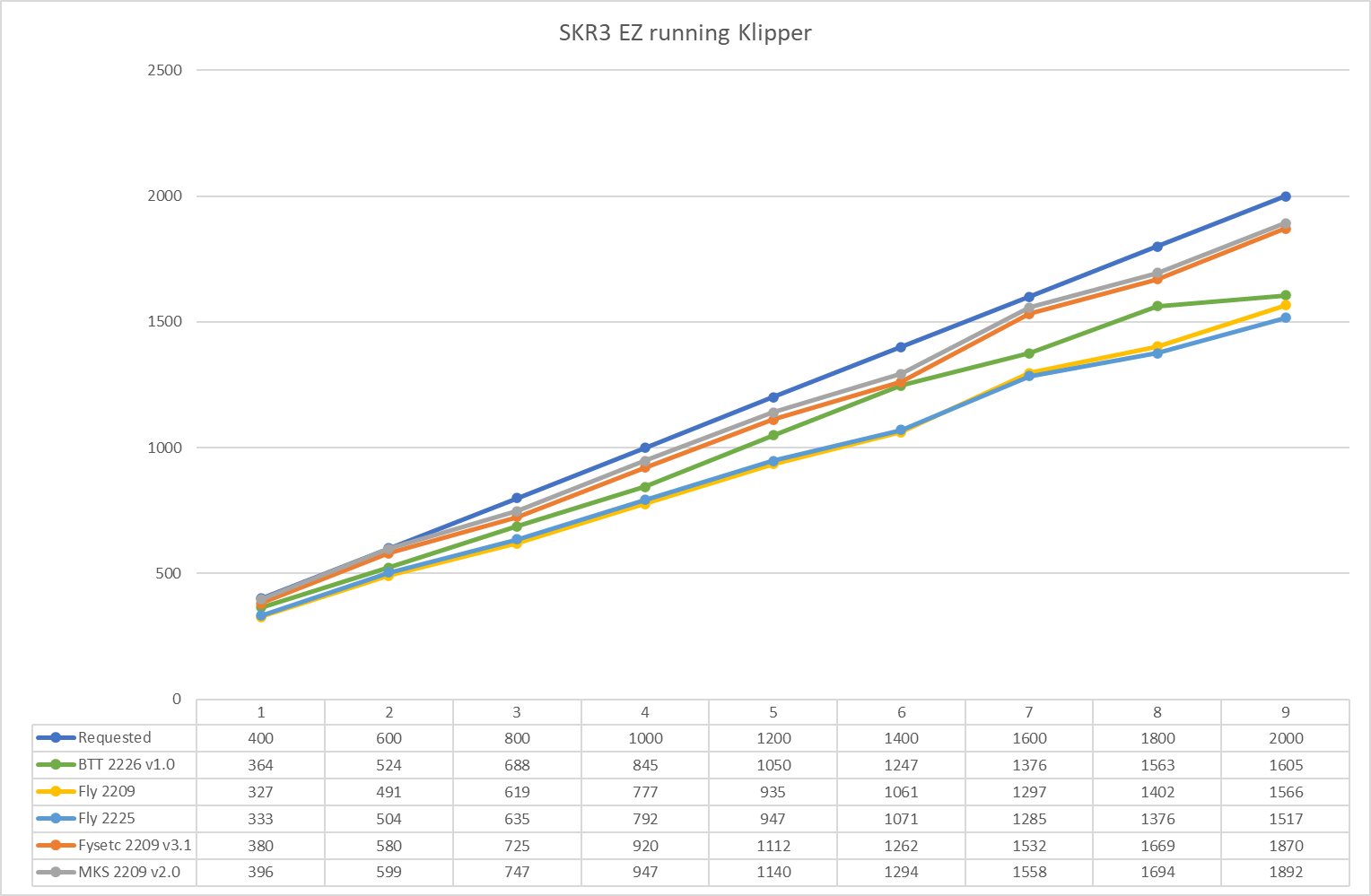
      You may notice that the EZ drivers are missing from the Klipper results. This is due to me incorrectly flashing Klipper when I started the testing and it set them at full current and burnt them out. Please also note that the BTT 2226 v1.0 drivers use a different sense resistor (0.150 ohm) than standard 22XX drivers (0.110 ohm) and I adjusted accordingly for that when running the tests.

      The results are pretty consistent between RRF and Klipper, which confirms the testing method and confirms that both firmwares calculate the required current using the sense resistor in a similar fashion.

      So how we overcome this incorrect current setting? The ideal is for the driver manufacturers to produce drivers that perform as expected, but that doesn't really help users who already have poor performing hardware. Fortunately we can counteract this by adjusting the sense resistor value configured in the firmware (this has only just been added to the STM32 port of RRF in 3.4.1). I found that a sense resistor value of 0.125 resulted in the Fly-E3-Pro performing correctly (when testing with RRF) and a sense resistor value of 0.140 resulting in the Fly 2209 drivers performing correctly (when testing with RRF).

      Further work needs to be carried out to validate the sense resistor values that users should be using with each driver to counteract poor driver performance

      Here are my full results driver_readings.xlsx

      posted in General Discussion
      jay_s_ukundefined
      jay_s_uk
    • Determining Max Speed and Acceleration

      There is a very handy guide for calculating the Max Speed and Acceleration your printer can handle here except the macro that it offers is aimed at klipper.
      I created 2 macros that do the same thing, one for coreXY printers and one for cartesian printers.
      These can be used in conjunction with the klipper guide.

      coreXY

      ; parameters
      ; A = maximum speed in mm/s
      ; B = maximum acceleration in mm/s2
      ; C = iterations
      ; D = Bound Size in mm
      ; E = smallPatternSize in mm
      
      ; Set up local variables
      var speedXCurrent = move.axes[0].speed
      var speedYCurrent = move.axes[1].speed
      var accelerationXCurrent = move.axes[0].acceleration
      var accelerationYCurrent = move.axes[1].acceleration
      var speedX = 0
      var speedY = 0
      var accelerationX = 0
      var accelerationY = 0
      var macroIterations = 0
      var bound = 0
      var smallPatternSize = 0
      var xPositionStart = 0
      var yPositionStart = 0
      var xPositionEnd = 0
      var yPositionEnd = 0
      var xEndstopHigh = sensors.endstops[0].highEnd
      var yEndstopHigh = sensors.endstops[1].highEnd
      var xPositionDifference = 0
      var yPositionDifference = 0
      var xMMPerFullStep = 0
      var yMMPerFullStep = 0
      
      if !exists(param.A)
      	set var.speedX = move.axes[0].speed / 60
      	set var.speedY = move.axes[1].speed / 60
      else 
      	set var.speedX = param.A
      	set var.speedY = param.A
      
      if !exists(param.B)
      	set var.accelerationX = move.axes[0].acceleration
      	set var.accelerationY = move.axes[1].acceleration
      else
      	set var.accelerationX = param.B
      	set var.accelerationY = param.B
      
      if !exists(param.C)
      	set var.macroIterations = 5
      else
      	set var.macroIterations = param.C
      
      if !exists(param.D)
      	set var.bound = 20
      else
      	set var.bound = param.D
      	
      if !exists(param.E)
      	set var.smallPatternSize = 20
      else
      	set var.smallPatternSize = param.E
      
      ; Large Pattern
      var x_min = move.axes[0].min + var.bound
      var x_max = move.axes[0].max - var.bound
      var y_min = move.axes[1].min + var.bound
      var y_max = move.axes[1].max - var.bound
      
      ; Small Pattern at Centre
      var x_centre = ( move.axes[0].max - move.axes[0].min ) / 2
      var y_centre = ( move.axes[1].max - move.axes[1].min ) / 2
      
      ; Set Small Pattern Box Around Centre Point
      var x_centre_min = var.x_centre - (var.smallPatternSize/2)
      var x_centre_max = var.x_centre + (var.smallPatternSize/2)
      var y_centre_min = var.y_centre - (var.smallPatternSize/2)
      var y_centre_max = var.y_centre + (var.smallPatternSize/2)
      
      M118 P0 S"Starting Speed Test"
      
      ; Home and get position for comparison later
      G28
      G32
      G90
      if var.xEndstopHigh
      	G0 X{move.axes[0].max - 1} F1800
      else
      	G0 X{move.axes[0].min + 1} F1800
      if var.yEndstopHigh
      	G0 Y{move.axes[1].max - 1} F1800
      else
      	G0 Y{move.axes[1].min + 1} F1800
      M400
      G4 S1
      set var.xPositionStart = move.axes[0].machinePosition
      set var.yPositionStart = move.axes[1].machinePosition
      
      echo "Start X Position is " ^ var.xPositionStart
      echo "Start Y Position is " ^ var.yPositionStart
      
      ; Set New Limits
      ; Speeds
      M203 X{var.speedX*60} Y{var.speedY*60}
      ; Accelerations
      M201 X{var.accelerationX} Y{var.accelerationY}
      
      ; Go to Start Position
      G0 X{var.x_min} Y{var.y_min} Z{var.bound + 10} F{var.speedX*60}
      
      ; Movement
      while iterations < var.macroIterations
      
      	; Large Pattern
      	; Diagonals
      	G0 X{var.x_min} Y{var.y_min} F{var.speedX*60}
      	G0 X{var.x_max} Y{var.y_max} F{var.speedX*60}
      	G0 X{var.x_min} Y{var.y_min} F{var.speedX*60}
      	G0 X{var.x_max} Y{var.y_min} F{var.speedX*60}
      	G0 X{var.x_min} Y{var.y_max} F{var.speedX*60}
      	G0 X{var.x_max} Y{var.y_min} F{var.speedX*60}
      
      	; Box
      	G0 X{var.x_min} Y{var.y_min} F{var.speedX*60}
      	G0 X{var.x_min} Y{var.y_max} F{var.speedX*60}
      	G0 X{var.x_max} Y{var.y_max} F{var.speedX*60}
      	G0 X{var.x_max} Y{var.y_min} F{var.speedX*60}
      
      	; Small Pattern
      	; Diagonals
      	G0 X{var.x_centre_min} Y{var.y_centre_min} F{var.speedX*60}
      	G0 X{var.x_centre_max} Y{var.y_centre_max} F{var.speedX*60}
      	G0 X{var.x_centre_min} Y{var.y_centre_min} F{var.speedX*60}
      	G0 X{var.x_centre_max} Y{var.y_centre_min} F{var.speedX*60}
      	G0 X{var.x_centre_min} Y{var.y_centre_max} F{var.speedX*60}
      	G0 X{var.x_centre_max} Y{var.y_centre_min} F{var.speedX*60}
      
      	; Box
      	G0 X{var.x_centre_min} Y{var.y_centre_min} F{var.speedX*60}
      	G0 X{var.x_centre_min} Y{var.y_centre_max} F{var.speedX*60}
      	G0 X{var.x_centre_max} Y{var.y_centre_max} F{var.speedX*60}
      	G0 X{var.x_centre_max} Y{var.y_centre_min} F{var.speedX*60}
      
      ; Restore Limits
      ; Speeds
      M203 X{var.speedXCurrent} Y{var.speedYCurrent}
      ; Accelerations
      M201 X{var.accelerationXCurrent} Y{var.accelerationYCurrent}
      
      ; Go back to 1mm from endstops and measure distance to endstop for Comparison
      G90
      if var.xEndstopHigh
      	G0 X{move.axes[0].max - 1} F1800
      	M400
      	G4 S1
      	G91
      	G1 H4 X{move.axes[0].max} F60
      	G90
      	M400
      	G4 S1
      	set var.xPositionEnd = move.axes[0].machinePosition - 1
      else
      	G0 X{move.axes[0].min + 1} F1800
      	M400
      	G4 S1
      	G91
      	G1 H4 X{-move.axes[0].max} F60
      	G90
      	M400
      	G4 S1
      	set var.xPositionEnd = move.axes[0].machinePosition + 1
      if var.yEndstopHigh
      	G0 Y{move.axes[1].max - 1} F1800
      	M400
      	G4 S1
      	G91
      	G1 H4 Y{move.axes[1].max} F60
      	M400
      	G4 S1
      	set var.yPositionEnd = move.axes[1].machinePosition - 1
      else
      	G0 Y{move.axes[1].min + 1} F1800
      	M400
      	G4 S1
      	G91
      	G1 H4 Y{-move.axes[1].max} F60
      	M400
      	G4 S1
      	set var.yPositionEnd = move.axes[1].machinePosition + 1
      
      echo "End X Position is " ^ var.xPositionEnd
      echo "End Y Position is " ^ var.yPositionEnd
      set var.xPositionDifference = abs(var.xPositionStart - var.xPositionEnd)
      set var.yPositionDifference = abs(var.yPositionStart - var.yPositionEnd)
      
      echo "X difference is " ^ var.xPositionDifference
      echo "Y difference is " ^ var.yPositionDifference
      
      set var.xMMPerFullStep = (1 / move.axes[0].stepsPerMm) + (1 / move.axes[0].stepsPerMm / move.axes[0].microstepping.value)
      set var.yMMPerFullStep = (1 / move.axes[1].stepsPerMm) + (1 / move.axes[1].stepsPerMm / move.axes[1].microstepping.value)
      
      if var.xPositionDifference >= var.xMMPerFullStep
      	M118 P0 S"There has been some skipping detected on the X axis. Please lower your acceleration or speed and test again"
      else
      	M118 P0 S"There has been no skipping detected on the X axis"
      
      if var.yPositionDifference >= var.yMMPerFullStep
      	M118 P0 S"There has been some skipping detected on the Y axis. Please lower your acceleration or speed and test again"
      else
      	M118 P0 S"There has been no skipping detected on the Y axis"
      

      cartesian

      ; parameters
      ; A = maximum speed in mm/s
      ; B = maximum acceleration in mm/s2
      ; C = iterations
      ; D = Bound Size in mm
      ; E = smallPatternSize in mm
      ; F = Axis to be tested, either F"X" or F"Y" is valid
      
      ; Set up local variables
      var speedXCurrent = move.axes[0].speed
      var speedYCurrent = move.axes[1].speed
      var accelerationXCurrent = move.axes[0].acceleration
      var accelerationYCurrent = move.axes[1].acceleration
      var speedX = 0
      var speedY = 0
      var accelerationX = 0
      var accelerationY = 0
      var macroIterations = 0
      var bound = 0
      var smallPatternSize = 0
      var testAxis = 0
      var xPositionStart = 0
      var yPositionStart = 0
      var xPositionEnd = 0
      var yPositionEnd = 0
      var xEndstopHigh = sensors.endstops[0].highEnd
      var yEndstopHigh = sensors.endstops[1].highEnd
      var xPositionDifference = 0
      var yPositionDifference = 0
      var xMMPerFullStep = 0
      var yMMPerFullStep = 0
      
      if !exists(param.A)
      	set var.speedX = move.axes[0].speed / 60
      	set var.speedY = move.axes[1].speed / 60
      else 
      	set var.speedX = param.A
      	set var.speedY = param.A
      
      if !exists(param.B)
      	set var.accelerationX = move.axes[0].acceleration
      	set var.accelerationY = move.axes[1].acceleration
      else
      	set var.accelerationX = param.B
      	set var.accelerationY = param.B
      
      if !exists(param.C)
      	set var.macroIterations = 5
      else
      	set var.macroIterations = param.C
      
      if !exists(param.D)
      	set var.bound = 20
      else
      	set var.bound = param.D
      	
      if !exists(param.E)
      	set var.smallPatternSize = 20
      else
      	set var.smallPatternSize = param.E
      
      if !exists(param.F)
      	abort "No Axis has been set using parameters"
      elif param.F = "X"
      	set var.testAxis = 0
      elif param.F = "Y"
      	set var.testAxis = 1	
      else
      	abort "Only X or Y axis can be used"
      
      ; Large Pattern
      var x_min = move.axes[0].min + var.bound
      var x_max = move.axes[0].max - var.bound
      var y_min = move.axes[1].min + var.bound
      var y_max = move.axes[1].max - var.bound
      
      ; Small Pattern at Centre
      var x_centre = ( move.axes[0].max - move.axes[0].min ) / 2
      var y_centre = ( move.axes[1].max - move.axes[1].min ) / 2
      
      ; Set Small Pattern Box Around Centre Point
      var x_centre_min = var.x_centre - (var.smallPatternSize/2)
      var x_centre_max = var.x_centre + (var.smallPatternSize/2)
      var y_centre_min = var.y_centre - (var.smallPatternSize/2)
      var y_centre_max = var.y_centre + (var.smallPatternSize/2)
      
      M118 P0 S"Starting Speed Test"
      
      ; Home and get position for comparison later
      G28
      G32
      G90
      
      if var.testAxis = 0
      	if var.xEndstopHigh
      		G0 X{move.axes[0].max - 1} F1800
      	else
      		G0 X{move.axes[0].min + 1} F1800
      	M400
      	G4 S1
      	set var.xPositionStart = move.axes[0].machinePosition
      	echo "Start X Position is " ^ var.xPositionStart
      
      if var.testAxis = 1
      	if var.yEndstopHigh
      		G0 Y{move.axes[1].max - 1} F1800
      	
      	else
      		G0 Y{move.axes[1].min + 1} F1800
      	M400
      	G4 S1
      	set var.yPositionStart = move.axes[1].machinePosition
      	echo "Start Y Position is " ^ var.yPositionStart
      
      ; Set New Limits
      ; Speeds
      M203 X{var.speedX*60} Y{var.speedY*60}
      ; Accelerations
      M201 X{var.accelerationX} Y{var.accelerationY}
      
      ; Go to Start Position
      
      if var.testAxis = 0
      	G0 X{var.x_min} Z{var.bound + 10} F{var.speedX*60}
      
      if var.testAxis = 1
      	G0 Y{var.y_min} Z{var.bound + 10} F{var.speedX*60}
      
      if var.testAxis = 0
      	; Movement
      	while iterations < var.macroIterations
      
      		; Large Pattern
      		; Large Line
      		G0 X{var.x_min} F{var.speedX*60}
      		G0 X{var.x_max} F{var.speedX*60}
      		G0 X{var.x_min} F{var.speedX*60}
      		G0 X{var.x_max} F{var.speedX*60}
      
      		; Small Pattern
      		; Small Line
      		G0 X{var.x_centre_min} F{var.speedX*60}
      		G0 X{var.x_centre_max} F{var.speedX*60}
      		G0 X{var.x_centre_min} F{var.speedX*60}
      		G0 X{var.x_centre_max} F{var.speedX*60}
      
      if var.testAxis = 1
      	; Movement
      	while iterations < var.macroIterations
      
      		; Large Pattern
      		; Large Line
      		G0 Y{var.y_min} F{var.speedX*60}
      		G0 Y{var.y_max} F{var.speedX*60}
      		G0 Y{var.y_min} F{var.speedX*60}
      		G0 Y{var.y_max} F{var.speedX*60}
      
      		; Small Pattern
      		; Small Line
      		G0 Y{var.y_centre_min} F{var.speedX*60}
      		G0 Y{var.y_centre_max} F{var.speedX*60}
      		G0 Y{var.y_centre_min} F{var.speedX*60}
      		G0 Y{var.y_centre_max} F{var.speedX*60}
      
      ; Restore Limits
      ; Speeds
      M203 X{var.speedXCurrent} Y{var.speedYCurrent}
      ; Accelerations
      M201 X{var.accelerationXCurrent} Y{var.accelerationYCurrent}
      
      ; Go back to 1mm from endstops and measure distance to endstop for Comparison
      if var.testAxis = 0
      	if var.xEndstopHigh
      		G0 X{move.axes[0].max - 1} F1800
      		M400
      		G4 S1
      		G91
      		G1 H4 X{move.axes[0].max} F60
      		G90
      		M400
      		G4 S1
      		set var.xPositionEnd = move.axes[0].machinePosition - 1
      	else
      		G0 X{move.axes[0].min + 1} F1800
      		M400
      		G4 S1
      		G91
      		G1 H4 X{-move.axes[0].max} F60
      		G90
      		M400
      		G4 S1
      		set var.xPositionEnd = move.axes[0].machinePosition + 1
      	G90
      	echo "End X Position is " ^ var.xPositionEnd
      	set var.xPositionDifference = abs(var.xPositionStart - var.xPositionEnd)
      	echo "X difference is " ^ var.xPositionDifference
      	set var.xMMPerFullStep = (1 / move.axes[0].stepsPerMm) + (1 / move.axes[0].stepsPerMm / move.axes[0].microstepping.value) ; set the check value to a full step + 1 microstep. mainly due to round with only 3 decemal places
      	if var.xPositionDifference >= var.xMMPerFullStep
      		M118 P0 S"There has been some skipping detected on the X axis. Please lower your acceleration or speed and test again"
      	else
      		M118 P0 S"There has been no skipping detected on the X axis"
      
      if var.testAxis = 1
      	if var.yEndstopHigh
      		G0 Y{move.axes[1].max - 1} F1800
      		M400
      		G4 S1
      		G91
      		G1 H4 Y{move.axes[1].max} F60
      		M400
      		G4 S1
      		set var.yPositionEnd = move.axes[1].machinePosition - 1
      	else
      		G0 Y{move.axes[1].min + 1} F1800
      		M400
      		G4 S1
      		G91
      		G1 H4 Y{-move.axes[1].max} F60
      		M400
      		G4 S1
      		set var.yPositionEnd = move.axes[1].machinePosition + 1
      	echo "End Y Position is " ^ var.yPositionEnd
      	set var.yPositionDifference = abs(var.yPositionStart - var.yPositionEnd)
      	echo "Y difference is " ^ var.yPositionDifference
      	set var.yMMPerFullStep = (1 / move.axes[1].stepsPerMm) + (1 / move.axes[1].stepsPerMm / move.axes[1].microstepping.value) ; set the check value to a full step + 1 microstep. mainly due to round with only 3 decemal places
      	if var.yPositionDifference >= var.yMMPerFullStep
      		M118 P0 S"There has been some skipping detected on the Y axis. Please lower your acceleration or speed and test again"
      	else
      		M118 P0 S"There has been no skipping detected on the Y axis"
      

      Both of these scripts accept parameters to adjust the settings (and these are listed at the top of each macro). Once they have ran, they will tell you whether a skip of more than 1 full step has occurred.
      The macros will automatically work regardless of whether your endstops are low or high.
      The cartesian macro will abort if an axis (X or Y) is not passed through as a parameter.
      If no other parameters are used, the default config.g settings will be used.
      If custom parameters are used, the default config.g settings will be restored at the end of the macro.

      Warning 1: They won't work with sensorless homing based printers unless you edit the scripts to include all the correct settings just above the G1 H4 measurement moves

      Warning 2: If the moves commanded have too high acceleration or speed they will skip. There is no protection against this and you may damage your printer. Make sure you are prepared to press the emergency stop button whilst running this

      I'm interested in any feedback people have and whether the scripts work ok for you.
      Both have been tested on 3.4.5 and should be fine on 3.5betaX

      posted in Tuning and tweaking
      jay_s_ukundefined
      jay_s_uk
    • Fly Screens are now Open Source

      About 18 months ago, @FLY announced he had made 2 new screens (4.3" and 7") which could be used with RRF https://forum.duet3d.com/topic/18742/i-made-a-new-paneldue
      At the time, there was disappointment that the firmware running on them was closed source.
      Fast forward to today and I am pleased to announce that the firmware is now open source and can be found here for both the 4.3" and 7".
      I have also written some basic instructions about how to get the IDE up and running, as well as how to compile the firmware and edit the code/UI.

      posted in Accessories and Add-ons
      jay_s_ukundefined
      jay_s_uk
    • LPC/STM32F4 port of RepRap Firmware 3.3.x+ with ESP32 Support

      @gloomyandy and TeamGloomy have just uploaded a stable release of the STM32F4 and LPC port of RepRapFirmware. We support both WiFi and SBC modes.
      The ESP32 support allows quicker upload speeds (1.6Mb/s) compared to the ESP8266 (500Kb/s). ESP32 adapters are only supported on STM32F4 boards.

      For details of changes for LPC/STM versions see here

      We support the following boards:

      LPC

      • Azsmz Mini
      • Azteeg X5 Mini v1.1
      • Azteeg X5 Mini v2
      • Azteeg X5 Mini v3
      • fly-CDY
      • MKS Sbase v1.3
      • MKS SGen L v1.0
      • MKS SGen L v2.0
      • ReArm
      • SKR v1.1
      • SKR v1.3
      • SKR v1.4 (both the standard and turbo versions)
      • SKR E3 Turbo
      • Smoothieboard

      STM32F4

      • Fly-407ZG
      • Fly-CDYv2
      • Fly-E3
      • Fly-E3-Pro
      • Fysetc Spider 407 Version
      • SKR v2
      • SKR-RRF-E3 + Expansion Board
      • SKR Pro v1.1
      • SKR Pro v1.2
      • BTT GTR v1.0

      Firmware Release files

      Can be found here

      WiFi Users

      As well as updating the firmware, you need to update the following:

      • ESP8266 and ESP32 firmware V1.26-05 from here. Instructions for LPC are here, STM32 ESP8266 are here and STM32 ESP32 are here
      • DWC inline with the firmware version from here.

      SBC Users

      Please follow the instructions from here for LPC and here for STM32

      General Info

      For more information on installing and configuring the firmware please see Wiki

      For help with generating RRF configuration files please see the online configuration tool (which has been updated for this release):
      RRF Configurator

      For help and general discussion please use the discord server:
      Discord Channel.

      Any restrictions/differences between the Duet3D release and the LPC release are detailed here.
      Any restrictions/differences between the Duet3D release and the STM32F4 release are detailed here.

      posted in RepRapFirmware on other controllers
      jay_s_ukundefined
      jay_s_uk
    • STM32F4 port of RepRap Firmware 3.1.x+

      @gloomyandy has just uploaded beta test versions of an experimental STM32F4 port of RepRap Firmware V3.1.x+. The firmware files can be found here: Google Drive

      This port is an enhanced version of the RepRap Firmware LPC176x port and much of the documentation/features etc. applies to both.
      Currently the following boards are supported:
      BTT SKR Pro V1.1
      BTT SKR Pro V1.2
      BTT GTR V1.0 (The drivers on the expansion board are not currently supported)

      Two versions of the firmware are provided:
      firmware-wifi.bin supports access by an ESP8266 WiFi module.
      firmware-sbc.bin supports connection to a Raspberry Pi SBC.
      Both versions have USB and serial ports enabled.

      For more information on installing and configuring the firmware please see the STM32F4 sections of the Wiki:
      Github Wiki

      For help with generating RRF configuration files please see the online configuration tool (which has been updated for this release):
      RRF Configurator

      For help and general discussion please use the discord server:
      Discord Channel

      Please note the following:

      • The WiFi version of this firmware requires updated firmware on the ESP8266 (it removes the small number of active socket limitation used with the LPC version). The updated ESP8266 firmware is provided in the link above (see the WiKi for programming details).

      • The SBC version of this firmware removes many of the limitations present in the LPC port (which are due to memory constraints), because of this the STM32F4 version now uses the standard Duet3D SBC RPi software not the version modified for the LPC.

      • As with the LPC version of RRF the WiFi module and SBC is connected via the EXP1 and EXP2 headers. However it should be noted that the orientation of these headers is different on the STM32F4 boards which may make using existing adaptors difficult.

      Adaptor boards for the WiFi and SBC connections can be purchased from @PCR here

      PLEASE DO NOT LEAVE ANY HARDWARE RUNNING THIS FIRMWARE UNATTENDED.
      This version is very new and has only received a small amount of testing. It may be used to control heaters and other hardware that in some situations could be dangerous. Please monitor operation carefully and use this firmware at your own risk.

      posted in STM
      jay_s_ukundefined
      jay_s_uk
    • Fly-RRF-36 RP2040 Based CAN-FD Toolboard

      I am pleased to announce that our first RP2040 based CAN-FD in now available for sale at https://www.aliexpress.com/item/1005005710321309.html
      This toolboard is compatible with STM32F4 boards when combined with an spican module, STM32H7 boards and Duet3D 3 series boards. You must be using RRF 3.5beta4. The toolboards include an LIS3DH accelerometer onboard as well as support for Neopixels.
      Information on the toolboard can be found here https://teamgloomy.github.io/fly_rrf_36_general.html and the schematic can be found here https://github.com/Mellow-3D/Fly-RRF-36/blob/master/Hardware/Schematic_Fly_RRF-36.pdf

      posted in Other control boards
      jay_s_ukundefined
      jay_s_uk

    Latest posts made by jay_s_uk

    • RE: Dead driver or dying board?

      @kazolar said in Dead driver or dying board?:

      M906 Y1600:1600 U1600:1600 X2000 V2000 W2000 A2000 Z2000:2000:2000:2000 E750:750:750:750 I50 ; set motor currents (mA) and motor idle factor in per cent

      This line is wrong. You can't set a drive current per motor on an axis, only on extruders.

      This would be the correct line to use

      M906 Y1600 U1600 X2000 V2000 W2000 A2000 Z2000 E750:750:750:750 I50 ; set motor currents (mA) and motor idle factor in per cent
      
      posted in Duet Hardware and wiring
      jay_s_ukundefined
      jay_s_uk
    • RE: [3.6.0-rc.2] Code 3 move error

      @MaxGyver you can use the events system to setup what you want to happen on loss of CAN board https://docs.duet3d.com/en/User_manual/RepRapFirmware/Events

      posted in Beta Firmware
      jay_s_ukundefined
      jay_s_uk
    • RE: 3.6 RC3 SHT36V3MAX Duet Mini 5+

      @smaaash As the SHT36 is an unofficial board, all the builds can be found in gloomyandy's github repo https://github.com/gloomyandy/RRFBuild/tree/v3.6-dev/releases/3.6.0-rc.2/expansion

      posted in Firmware installation
      jay_s_ukundefined
      jay_s_uk
    • RE: 3.6 RC3 SHT36V3MAX Duet Mini 5+

      @smaaash we haven't released a 3.6rc3 version, only 3.6rc2. You're best off downgrading to 3.6rc2. You shouldn't run 3.5.4 with 3.6rc3 as so much has changed

      posted in Firmware installation
      jay_s_ukundefined
      jay_s_uk
    • RE: chamber sensor for temperature monitoring

      @Arminas nothing jumps out at me so its one for @chrishamm to comment why there is a second sensor showing up on the extras tab for the chamber

      posted in 3D Printing General Chat
      jay_s_ukundefined
      jay_s_uk
    • RE: chamber sensor for temperature monitoring

      @Arminas can you post your whole config so we can check theres nothing else wrong?

      posted in 3D Printing General Chat
      jay_s_ukundefined
      jay_s_uk
    • RE: chamber sensor for temperature monitoring

      @Arminas it shouldn't be showing now its bound to a heater. have you done a full restart/refresh?
      what firmware version?

      posted in 3D Printing General Chat
      jay_s_ukundefined
      jay_s_uk
    • RE: chamber sensor for temperature monitoring

      @Arminas your T value is wrong in the M950. It should be T2 not T3

      posted in 3D Printing General Chat
      jay_s_ukundefined
      jay_s_uk
    • RE: Ringing in Y axis (Linear guide system, coreXY design)

      @JayT the closer to the nozzle the better. There are mounts you can print that let you mount an accelerometer directly to the nozzle (just for data capture)

      posted in General Discussion
      jay_s_ukundefined
      jay_s_uk
    • RE: DWC overlay on DSF

      @Tech_Sam03 I don't think DWC works at all well on 5 or 7 inch screens. If you can hold off I would wait longer...

      posted in General Discussion
      jay_s_ukundefined
      jay_s_uk