Duet3D Logo Duet3D
    • Tags
    • Documentation
    • Order
    • Register
    • Login

    How to derive leadscrew / motor positions

    Scheduled Pinned Locked Moved Solved
    Documentation
    3
    8
    476
    Loading More Posts
    • Oldest to Newest
    • Newest to Oldest
    • Most Votes
    Reply
    • Reply as topic
    Log in to reply
    This topic has been deleted. Only users with topic management privileges can see it.
    • bilschundefined
      bilsch
      last edited by

      This is related to a thread I started on https://forum.duet3d.com/topic/28055/4-independent-z-axis-tilt?_=1649773992041

      I've seen in various configurations for my printer ( voron 2.4 but that does not really matter here ) different values for my printer:

      M671 X-60:-10:360:370 Y0:395:395:0 S20 ; Define Z belts locations (Front_Left, Back_Left, Back_Right, Front_Right)
      ; Position of the bed leadscrews.. 4 Coordinates

      What I want to know is HOW do I come up with those points? What are the measurements referenced against? ( the doc does not help me - maybe I'm just too dense! )

      do I reference the values for the stepper positions by reference from 0,0 front left of the frame?

      For what its worth the homing, after I tweaked the order and values from a config, got a LOT closer 😉

      jay_s_ukundefined 1 Reply Last reply Reply Quote 0
      • jay_s_ukundefined
        jay_s_uk @bilsch
        last edited by

        @bilsch for the v2.4 its the location of the pivot point between the gantry and the z rail in relation to 0,0

        Owns various duet boards and is the main wiki maintainer for the Teamgloomy LPC/STM32 port of RRF. Assume I'm running whatever the latest beta/stable build is

        bilschundefined 1 Reply Last reply Reply Quote 0
        • bilschundefined
          bilsch @jay_s_uk
          last edited by

          @jay_s_uk Not sure what you mean by pivot point. Is this like mid point between the belts and the pulley or something?

          jay_s_ukundefined 1 Reply Last reply Reply Quote 0
          • jay_s_ukundefined
            jay_s_uk @bilsch
            last edited by

            @bilsch this bit
            83f366fb-dc60-4e3d-bd1f-d8af1bbad556-image.png

            Owns various duet boards and is the main wiki maintainer for the Teamgloomy LPC/STM32 port of RRF. Assume I'm running whatever the latest beta/stable build is

            bilschundefined 1 Reply Last reply Reply Quote 0
            • bilschundefined
              bilsch @jay_s_uk
              last edited by

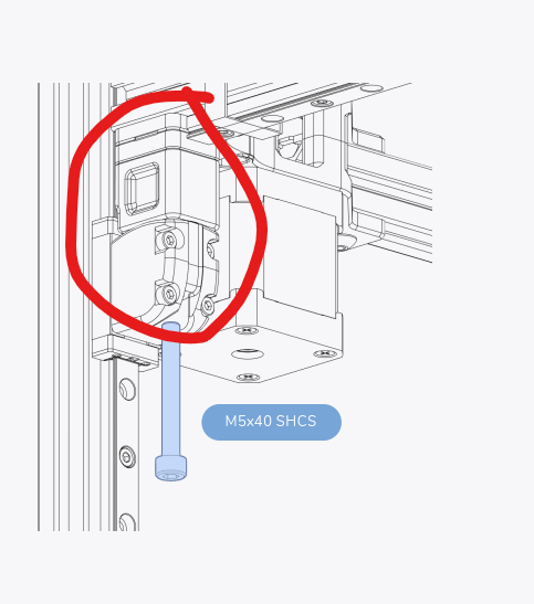
              @jay_s_uk ah got it ok!

              So I would just want to use my caliper or whatever to measure from each corner to that center point of the screw right? Is it a straight angle or squared?

              Or is it from 0,0 the distance between?

              jay_s_ukundefined 1 Reply Last reply Reply Quote 0
              • jay_s_ukundefined
                jay_s_uk @bilsch
                last edited by

                @bilsch it the X and Y offset from 0,0
                So if the first one is 10mm to the left and 10mm in front it would be X-10 Y-10 and so on.
                You can use calipers or the model to measure it (to the centre of the screw).
                The measurements don't need to be exact, within a few mm is fine

                Owns various duet boards and is the main wiki maintainer for the Teamgloomy LPC/STM32 port of RRF. Assume I'm running whatever the latest beta/stable build is

                bilschundefined 1 Reply Last reply Reply Quote 0
                • bilschundefined
                  bilsch @jay_s_uk
                  last edited by

                  @jay_s_uk Awesome thanks so much!

                  1 Reply Last reply Reply Quote 1
                  • droftartsundefined
                    droftarts administrators
                    last edited by

                    I've added a bit extra to the M671 documentation in the GCode dictionary:

                    • The X and Y coordinates in M671 are measured from the origin X0,Y0 set by M208. Measure to the pivot point of the bed where it connects to the Z axis. This is often each leadscrew, but may also be offset from the leadscrew if the bed rests on a carriage extending out from the leadscrew.
                    • The order of the X and Y coordinates is important; they relate to the order the motor drivers are defined in the M584 command. The first defined motor in M584 should be the first defined coordinates for X and Y in M671, and so on. For example, if you have M584 Z3:4:5 and M671 X[a]:[b]:[c] Y[a]:[b]:[c], the positions of X and Y for the motor on Z3 are defined by X[a],Y[a], Z4 by X[b],Y[b], and Z5 by X[c],Y[c].

                    Ian

                    Bed-slinger - Mini5+ WiFi/1LC | RRP Fisher v1 - D2 WiFi | Polargraph - D2 WiFi | TronXY X5S - 6HC/Roto | CNC router - 6HC | Tractus3D T1250 - D2 Eth

                    1 Reply Last reply Reply Quote 0
                    • droftartsundefined droftarts marked this topic as a question
                    • droftartsundefined droftarts has marked this topic as solved
                    • First post
                      Last post
                    Unless otherwise noted, all forum content is licensed under CC-BY-SA