G32 Error: Probe already triggered before probing move started
-
I'm installing a CR Touch on a Tevo Tornado and am getting this error: G32 Error: Probe already triggered before probing move started.
I have it wired like this...

Config.g...
; Configuration file for Duet WiFi (firmware version 3.3) ; executed by the firmware on start-up ; ; generated by RepRapFirmware Configuration Tool v3.3.10 on Tue May 10 2022 16:57:14 GMT-0400 (Eastern Daylight Time) ; General preferences M575 P1 S1 B57600 ; enable support for PanelDue G90 ; send absolute coordinates... M83 ; ...but relative extruder moves M550 P"TEVO" ; set printer name ; Network M552 S1 ; enable network M586 P0 S1 ; enable HTTP M586 P1 S0 ; disable FTP M586 P2 S1 ; enable Telnet ; Drives M569 P0 S1 ; physical drive 0 goes forwards M569 P1 S1 ; physical drive 1 goes forwards M569 P2 S1 ; physical drive 2 goes forwards M569 P3 S0 ; physical drive 3 goes forwards M584 X0 Y1 Z2 E3 ; set drive mapping M350 X16 Y16 Z16 E16 I1 ; configure microstepping with interpolation M92 X80.00 Y80.00 Z400.00 E932.00 ; set steps per mm M566 X900.00 Y900.00 Z60.00 E120.00 ; set maximum instantaneous speed changes (mm/min) M203 X6000.00 Y6000.00 Z180.00 E1200.00 ; set maximum speeds (mm/min) M201 X500.00 Y500.00 Z20.00 E250.00 ; set accelerations (mm/s^2) M906 X800 Y800 Z800 E800 I30 ; set motor currents (mA) and motor idle factor in per cent M84 S30 ; Set idle timeout ; Axis Limits M208 X0 Y0 Z0 S1 ; set axis minima M208 X360 Y366 Z400 S0 ; set axis maxima ; Endstops M574 X1 S1 P"!xstop" ; configure switch-type (e.g. microswitch) endstop for low end on X via pin !xstop M574 Y1 S1 P"!ystop" ; configure switch-type (e.g. microswitch) endstop for low end on Y via pin !ystop M574 Z1 S1 P"!zstop" ; configure switch-type (e.g. microswitch) endstop for low end on Z via pin !zstop ; Z-Probe M558 P9 R0.4 C"zprobe.in+zprobe.mod" H5 F1200 T6000 ; set Z probe type to effector and the dive height + speeds G31 P500 X0 Y0 Z2.5 ; set Z probe trigger value, offset and trigger height M557 X15:285 Y15:285 S20 ; define mesh grid ; Heaters ;M308 S0 P"bedtemp" Y"thermistor" T100000 B4138 ; configure sensor 0 as thermistor on pin bedtemp ;M950 H0 C"bedheat" T0 ; create bed heater output on bedheat and map it to sensor 0 ;M307 H0 B1 S1.00 ; enable bang-bang mode for the bed heater and set PWM limit ;M140 H0 ; map heated bed to heater 0 ;M143 H0 S120 ; set temperature limit for heater 0 to 120C ;M308 S1 P"e0temp" Y"thermistor" T100000 B4138 ; configure sensor 1 as thermistor on pin e0temp ;M950 H1 C"e0heat" T1 ; create nozzle heater output on e0heat and map it to sensor 1 ;M307 H1 B0 S1.00 ; disable bang-bang mode for heater and set PWM limit ;M143 H1 S280 ; set temperature limit for heater 1 to 280C ; Heaters V2 ; Heaters M308 S0 P"bedtemp" Y"thermistor" T100000 B4138 ; configure sensor 0 as thermistor on pin bedtemp M950 H0 C"bedheat" T0 ; create bed heater output on bedheat and map it to sensor 0 M307 H0 B0 S1.00 ; disable bang-bang mode for the bed heater and set PWM limit M140 H0 ; map heated bed to heater 0 M143 H0 S120 ; set temperature limit for heater 0 to 120C M308 S1 P"e0temp" Y"thermistor" T100000 B4138 ; configure sensor 1 as thermistor on pin e0temp M950 H1 C"e0heat" T1 ; create nozzle heater output on e0heat and map it to sensor 1 M307 H1 B0 S1.00 ; disable bang-bang mode for heater and set PWM limit M143 H1 S280 ; Fans M950 F0 C"fan0" Q500 ; create fan 0 on pin fan0 and set its frequency M106 P0 S0 H-1 ; set fan 0 value. Thermostatic control is turned off ; Tools M563 P0 S"BiquH2" D0 H1 F0 ; define tool 0 G10 P0 X0 Y0 Z0 ; set tool 0 axis offsets G10 P0 R0 S0 ; set initial tool 0 active and standby temperatures to 0C ; Custom settings M575 P1 S1 B57600 -
You have specified a P9 probe which is for a BLTouch.
But a BLTouch is not wired like that.
If the CR Touch works the same as a BLTouch you will need to wire it the same as a BLTouch.
Frederick
Printers: a E3D MS/TC setup and a RatRig Hybrid. Using Duet 3 hardware running 3.4.6
-
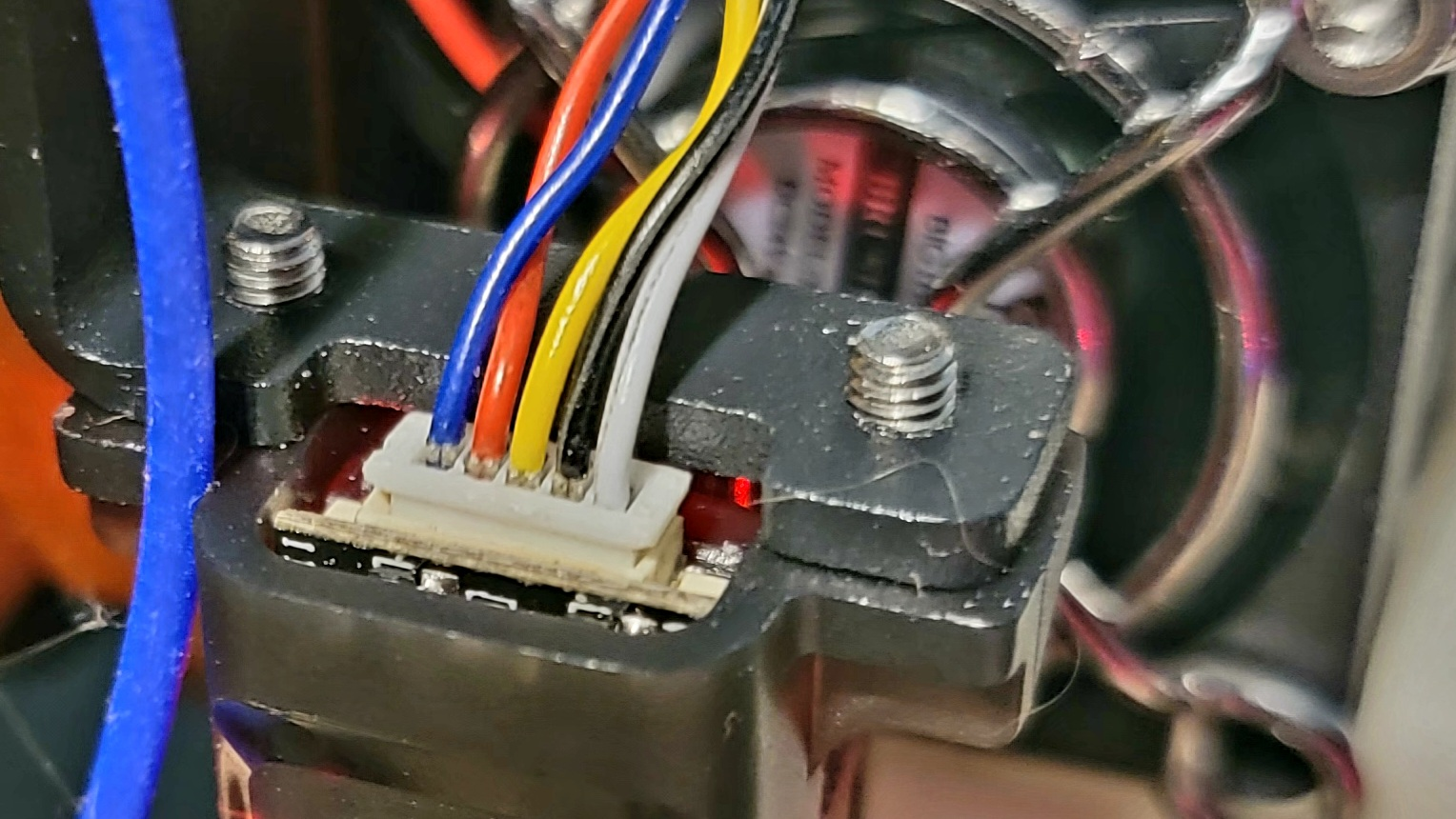
Wires coming out of the CR Touch
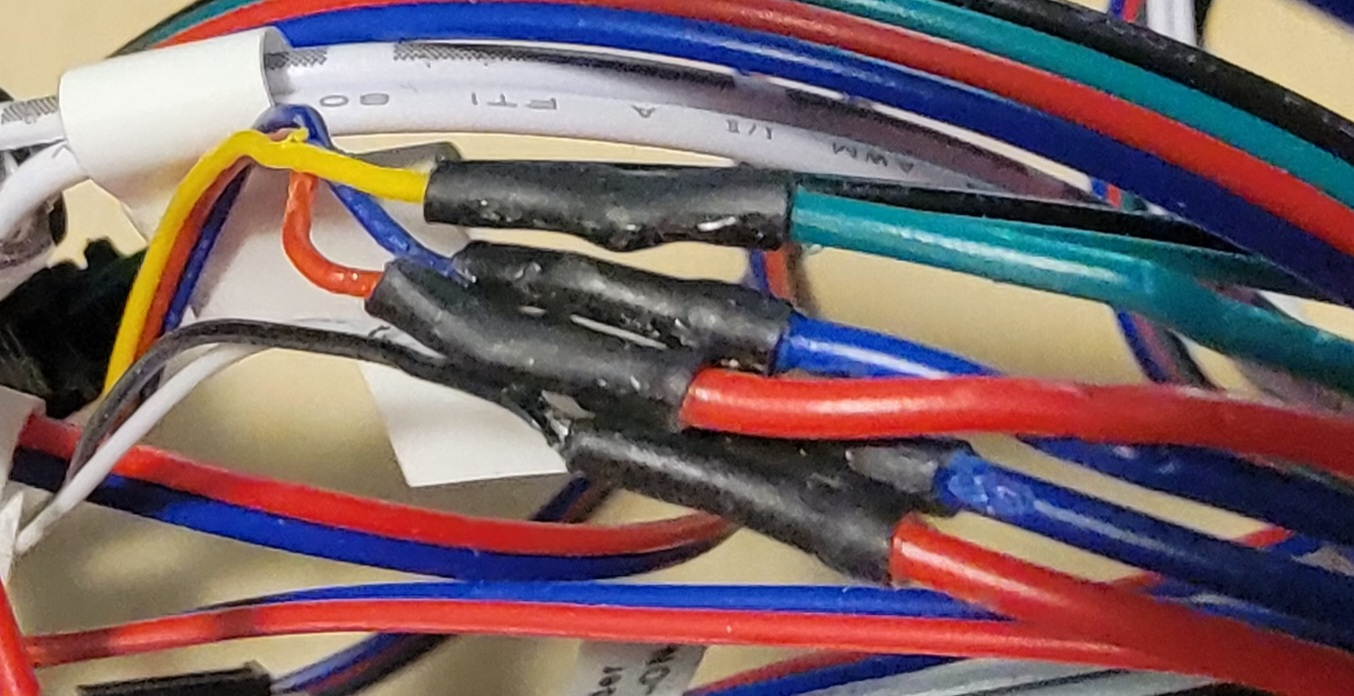
Wire extensions soldered on
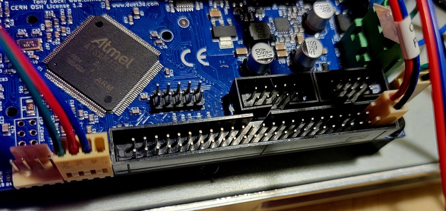
Connected to the board.
All connections ohmed out fine with no shorts.
-
@fcwilt Thanks for the quick reply...
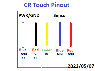
This is the photo of the CR Touch going into a Crealty board... it's the only pinout of the wires I could find for it. The only difference is that it says "out" instead of "mod". Other than that, I think I have wired it just as a BL Touch. Do you have a specific wire you think is wrong, or was that just a general comment?
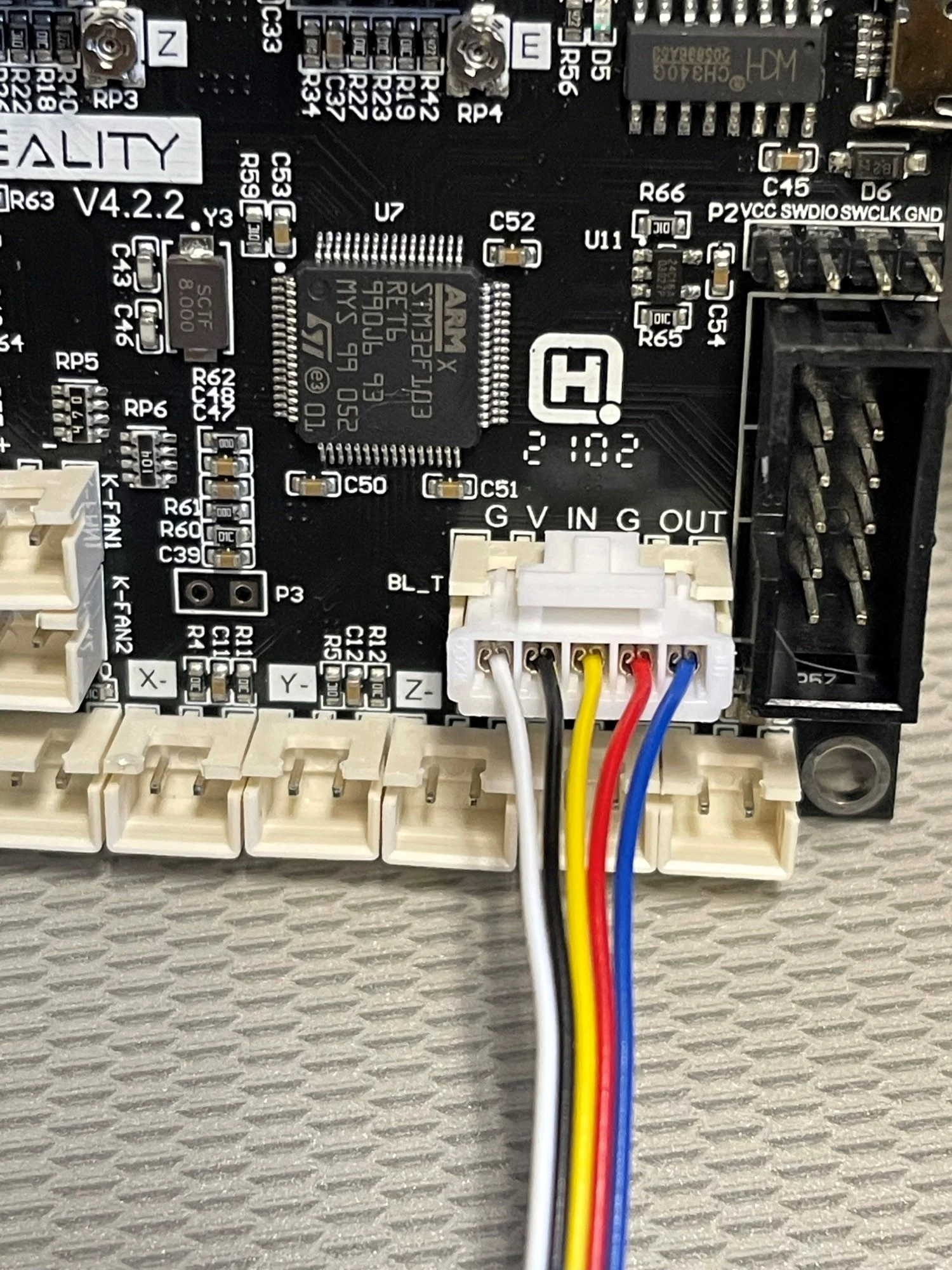
Someone has mentioned that the CR Touch is a clone of the BL Touch. That assumption could be the real problem.
-
Based on the docs the wiring is not correct nor is the M558.
Here is mine but I am using a Duex5 board so the pin name in the M950 will be different, it might be exp.8
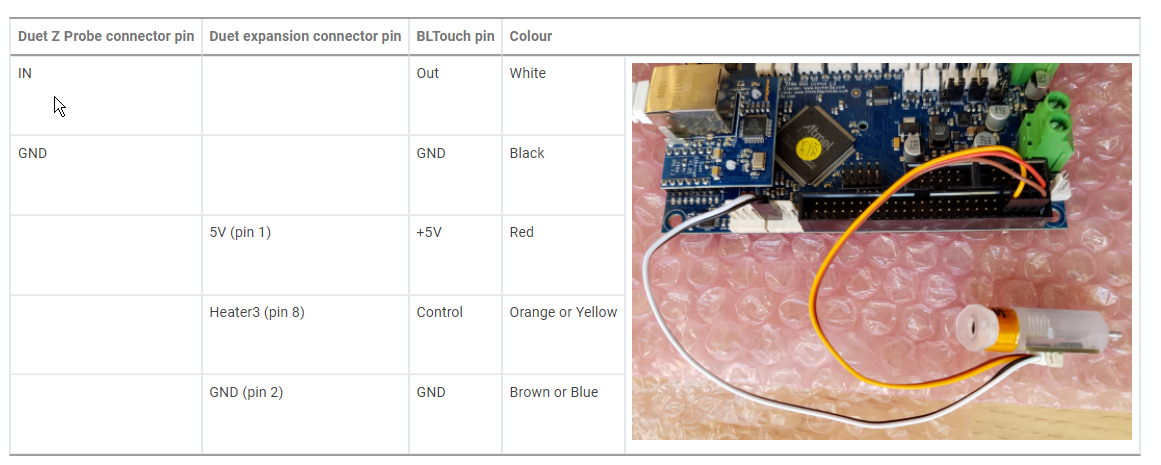
M950 S0 C"duex.pwm5"                      ; create servo pin 0 for BLTouch
M558 P9 C"^zprobe.in" H5 F120 T12000 R0.2 ; set Z probe type to BLtouch and set default parameters
Here is a picture of the wiring of a BLTouch using the Duet expansion header:
Frederick
Printers: a E3D MS/TC setup and a RatRig Hybrid. Using Duet 3 hardware running 3.4.6
-
@the-chairman Scroll down to BLTouch to see the creality wirings: https://docs.duet3d.com/en/User_manual/Connecting_hardware/Z_probe_connecting
-
@fcwilt and @Stephen6309 It's a big doc with lots of illustrations. Can you be more specific with the pic you want me to see? Maybe post it here? I'm just a noobie and a bit overwhelmed. but I'm really trying.
The documentation says "9 BLTouch OUT (Duet 3) and MOD (Duet 2 Maestro) can be configured to control deployment/retraction. MOD on Duet 2 WiFi/Ethernet is not PWM capable, so use heater pin on expansion port instead." I have a Duet 2 WiFi, so please translate.
-
@the-chairman On the page I posted, in the Page Content section click on BLTouch, and the wiring table is shown. Below that it show how to wire the BLTouch, but you need to use the creality wiring colors.
-
-
@stephen6309 & @fcwilt thanks to both of you... that really helps a lot. My mod wire needs to be connected to exp HEATER3. "exp" means expansion header. Cool. Simple enough to do.
Now, how do I define HEATER3 as the real "Mod"? Do I have to edit config.g and add it somewhere?
-
@the-chairman said in G32 Error: Probe already triggered before probing move started:
@stephen6309 & @fcwilt thanks to both of you... that really helps a lot. My mod wire needs to be connected to exp HEATER3. "exp" means expansion header. Cool. Simple enough to do.
Now, how do I define HEATER3 as the real "Mod"? Do I have to edit config.g and add it somewhere?
Go back and look at my configuration.
You use M950 to create the PWM output signal which deploys/retracts the probe pin.
You use M558 to specify the probe characteristics and which input pin is to be monitored for probe state.
These are commonly put into config.g. There are other ways but that might just confuse you at this point.
Frederick