Euclid probe and Z=0 datum
-
I recently installed a Euclid probe (dock-able probe similar to klicky probe). However I constantly get
Warning: the height map has a substantial Z offset. Suggest use Z-probe to establish Z=0 datum, then re-probe the mesh.My last G32 results were
16 points probed, min error -0.318, max error -0.122, mean -0.206, deviation 0.055
Height map saved to file 0:/sys/heightmap.csv
Warning: the height map has a substantial Z offset. Suggest use Z-probe to establish Z=0 datum, then re-probe the mesh.
Leadscrew adjustments made: -0.200 -0.200 -0.205, points used 3, (mean, deviation) before (-0.202, 0.002) after (0.000, 0.000)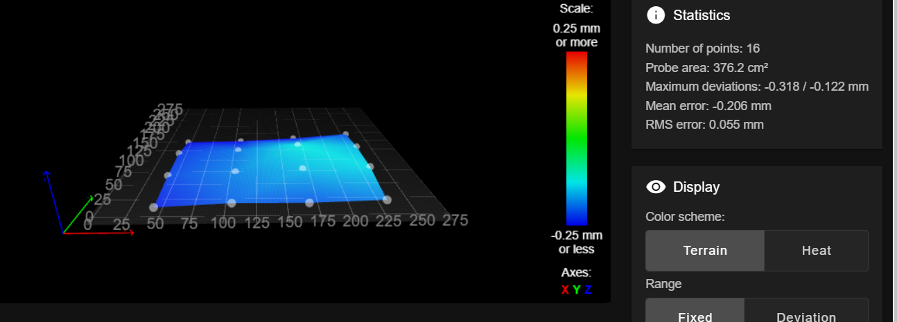
My config.g
M80 C"pson"													; Turns on the ATX power supply
G4 S1														; Wait for tool board
G90                                                			; send absolute coordinates...
M83                                                			; ...but relative extruder moves
M669 K1                                            			; select CoreXY mode
M955 P20.0 I14												; specify orientation of accelerometer(+Y,-X) on Toolboard 1LC with CAN address 20

; ====================== Network ===========================
; not supported on Duet 3 with SBC

; ======================= Drives ===========================
M569 P20.0 S0 D3                                      		; physical drive 0.0 goes backwards-Extruder
M569 P0.0 S0 D3                                    			; physical drive 0.1 goes backwards-X stepper
M569 P0.1 S0 D3                                    			; physical drive 0.2 goes backwards-Y stepper
M569 P0.3 S0                                       			; physical drive 0.3 goes backwards-Z left stepper
M569 P0.4 S0                                       			; physical drive 0.4 goes backwards-Z right front stepper
M569 P0.5 S0                                       			; physical drive 0.5 goes backwards-Z right rear stepper
M584 X0.0 Y0.1 Z0.3:0.4:0.5 E20.0                           ; set drive mapping Z3=Left center, Z4= Right front, Z5=Right rear

; ===================== Drive Settings =====================
M350 X16 Y16 Z16 E16 I1                            			; configure microstepping with interpolation XY .9 degree ZE 1.8 degree
M92 X200.00 Y200.00 Z400.00 E707.00                			; set steps per mm XY .9 degree ZE 1.8 degree - NF-Sunrise Maybe 683
M203 X5000.00 Y5000.00 Z800.00 E7200.00          			; (mm/min) Set maximum speeds mm per minute/60=mm per second
M201 X5000.00 Y5000.00 Z800.00 E5000.00			   		; (mm/second^2) Set per-axis and extruder print accelerations
M204 P2000 T8000								   			; (mm/second^2) Set print and travel accelerations
M566 X2000.00 Y2000.00 Z300.00 E5000.00						; (mm/min) Set maximum instantaneous speed changes
M906 X1600 Y1600 Z1400 E900 I30                   			; Set motor currents (mA) and motor idle factor in per cent
M84 S120                                           			; Set idle timeout

; ================ Independent Z Leveleing =================
M671 X-9.0:289:289 Y139.5:37.0:242.0 S10					; leadscrew pivot point:
M557 X30:245 Y50:225 P4										; Defines the grid Mesh Bed probing.

; ===================== Axis Limits ========================
M208 X-3 Y-10 Z0 S1                                   		; set axis minima
M208 X275 Y277 Z240 S0                             	; set axis maxima

; ======================= Endstops =========================
M574 X1 S1 P"20.io1.in"                              		; configure active-high endstop for high end on X via pin i01.in
M574 Y2 S1 P"0.io2.in"                              		; configure active-high endstop for high end on Y via pin i02.in
M574 Z1 S2				                          ; configure Z-probe endstop for low end on Z
;M591 D0 P1 C"20.io3.in" S1							  		; configure filament runout sensor for high end on extruder drive 0 via pin i03.in

; ======================== Z-Probe =========================
M558 P8 C"^20.io0.in" H5 F250 T10000    				               		; set Z probe type and the dive height + speed
G31 P500 X0.00 Y51.00 Z6.600                        		; set Z probe trigger value, offset and trigger height

; ======================== Heaters =========================
M308 S0 P"0.temp0" Y"thermistor" A"Bed" T100000 B4725 C0.0000000706             ; configure sensor 0 as thermistor on pin temp0
M308 S1 P"20.temp0" Y"thermistor" A"Hotend" T100000 B4680 C6.455513e-8   ; configure sensor 1 as thermistor on pin temp1-Matrix
M950 H0 C"0.out0" T0                                 		; create bed heater output on out0 and map it to sensor 0
M950 H1 C"20.out0" T1                                 		; create nozzle heater output on out1 and map it to sensor 1
M307 H0 R0.290 K0.119:0.000 D29.94 E1.35 S1.00 B0			;Set PID for bed heater POST RRF 3.4
M307 H1 R2.258 K0.262:0.297 D6.30 E1.35 S1.00 B0 V24.2		;Set PID for bed heater POST RRF 3.4
M140 H0                                            			; map heated bed to heater 0
M143 H0 S100                                       			; set temperature limit for heater 0 to 100C
M143 H1 S260                         						; Set temperature limit for heater 1 to 260C
M308 S10 Y"mcu-temp" P"0.mcu-temp"		                    ; defines sensor 10 as MCU temperature sensor

; ========================= Fans ===========================
M950 F0 C"20.out1" Q50		                            	; create fan 0 on pin out9 and set its frequency
M950 F1 C"20.out2" Q50										; create fan 0 on pin out9 and set its frequency
M106 P0 C"Tool Fan" H1 T40                                 ; set fan 0 value. Thermostatic control is turned on
M106 P1 C"Layer Fan" S0 H-1                                ; set fan 0 value. Thermostatic control is turned off

; ======================== Tools ===========================
M563 P0 D0 H1 F1                                 			; define tool 0
G10 P0 X0 Y0 Z0 R0 S0                              			; set tool 0 axis offsets

; ===================== Custom settings ====================
M564 H0                                   	   				; Let the Jog buttons work blv: added to allow jog buttons

; ====================== Miscellaneous =====================
M575 P1 S1 B57600                                  			; enable support for PanelDue
M575 P2 S1 B57600                                  			; enable support for BLV NeoPixels
M911 S10 R11 P"M913 X0 Y0 G91 M83 G1 Z3 E-5 F1000" 			; set voltage thresholds and actions to run on power loss
M950 J1 C"!0.io3.in"										; Create GPIO pin for On button wired NO
M581 T2 P1 S1 R0		                       				; T2-Run Trigger 2; P1-J1; S1-When button pressed; R0-trigger any time
M950 J2 C"!0.io4.in"										; Create GPIO pin for On button wired NO
M581 T3 P2 S1 R0		                       				; T3-Run Trigger 3; P2-J2; S1-When button pressed; R0-trigger any time
M582 T3														; when triggered run trigger3.g
bed.g
M561                      						   ; clear any bed transform
G91                    								; relative positioning
G1 H2 Z5         									; lift Z relative to current position
G1 H1 X-300 Y300 F15000								; move quickly to X or Y endstop and stop there (first pass)
G1 H1 X-300 F15000     								; home X axis
G1 H1 Y300 F15000      								; home Y axis
G1 X5 Y-5		       								; go back a few mm
G1 H1 X-5 F360       								; move slowly to X axis endstop once more (second pass)
G1 H1 Y300 F360       								; then move slowly to Y axis endstop
G90                    								; absolute positioning

echo "Undock Probe"

if sensors.probes[0].value[0]!=1000    				; if sensor is value other than 1000 do this
  ; uncomment next line to echo the probe deploy state
  ; echo "deployuser token = " ^sensors.probes[0].deployedByUser
  ; echo "Probe State = " ^sensors.probes[0].value[0]
  abort "deployprobe start value Probe already picked up.  Manually return probe to the dock"

if !sensors.probes[0].deployedByUser  				; If the probe is not deployed, deploy it
    M401											; Deploy probe

G1 X150.0 Y90.0 F15000								; go to first probe point
G30             									; home Z by probing the bed
G30 P0 X5 Y130 F300 Z-99999							; Probe near left lead screw position X0 Y137.5
G30 P1 X270 Y40 F3000 Z-99999 						; Probe near right rear lead screw position X335 Y10
G30 P2 X270 Y245.0 F6000 Z-99999 S3					; Probe near right rear lead screw position X335 Y265
G1 X150.0 Y90.0 F15000								; go to first probe point
G30             									; home Z by probing the bed
G29 S0												; Probe the bed, save the height map, and activate mesh bed compensation
M400												; wait for move to finish
M402												; dock probe
deployprobe.g
echo "Undock Probe"
if !move.axes[0].homed || !move.axes[1].homed     ; If the printer hasn't been homed, home it
    M98 P"0:/sys/homexy.g"
; uncomment next line to echo the probe deploy state
; echo "Object Model Deployuser token =" ^sensors.probes[0].deployedByUser
; uncomment next line to echo the probe value
; echo "Probe Value =" ^sensors.probes[0].value[0]
if sensors.probes[0].value[0]!=1000    ; if sensor is value other than 1000 do this
  ; uncomment next line to echo the probe deploy state
  ; echo "deployuser token = " ^sensors.probes[0].deployedByUser
  ; echo "Probe State = " ^sensors.probes[0].value[0]
  abort "deployprobe start value Probe already picked up.  Manually return probe to the dock"
; if we're here we know it's becasue the above is true which I assume is because you have an NC switch as a probe.
; echo "Passed first logic test to deploy probe"
echo "Probe Pickup macro running"
G0 X272 Y260 F3000               ; move to re-entry position
M400                          ; wait for moves to finish
G0 X272 Y277 F300              ; move to Preflight Position
G4 P500                       ; pause 0.5 seconds
M400                          ; wait for moves to finish
G0 X240 Y277 F300               ; move to Dock Side dock location
M400                          ; wait for moves to finish
echo "Probe Pickup complete"
retractprobe.g
G0 X200 Y277 F3000               ; move to ready position
M400                          ; wait for moves to finish
G0 X240 Y277  F3000              ; move to the entry position for the dock
M400                          ; wait for moves to finish
G0 X272 Y277  F300                ; move into the dock position
M400                          ; wait for moves to finish
G4 P250                       ; pause 250 usecs
G0 X272 Y240 F300               ; move to the side adjacent to the dock swiping the probe off
G0 X150 Y150 F6000              ; move to the side adjacent to the dock swiping the probe off
M400                          ; wait for moves to finish
echo "Probing complete"
My current setup
Duet 3 clone with RRF 3.4
24v PSU
Duet tool board v1.2
RPI4 on it's own dedicated PSU
5v PSU powering a latching relay and PSON to the Duet clone. The latching relay closes the neutral circuit for the main 24v PSU -
@dhusolo You need to home Z with the probe.
-
@stephen6309 It is homing Z with the probe. I actually figured it out. I had to add S-2 to both G30 commands in bed.g
-
@dhusolo said in Euclid probe and Z=0 datum:
@stephen6309 It is homing Z with the probe. I actually figured it out. I had to add S-2 to both G30 commands in bed.g
You only have a single tool configured. With a single tool you shouldn't need to use G30 S-2. If you do something else is not right.
Just FYI:
- You don't need to use M400 between G0 moves.
- You don't need to use M400 after G29 S0.
Just out of curiosity:
- Why do you have the G4 commands when deploying/retracting the probe?
- Did you verify that a single bed leveling pass is sufficient to always level the bed?
Thanks much.
Frederick
-
@fcwilt @fcwilt I used the macro templates from the Euclid probe website.
I have a railcore 250zl bed with independent leveling with kinematic mounts. I don't really have to deal with bed droppage too much. After I built it I ran numerous rounds of leadscrew leveling and the values were very consistent.
I've never had to use G30 S-2. I wasn't sure if it was because of the Euclid probe, a firmware issue, config issue or what the deal is. I've never had this happen before.
-
@dhusolo said in Euclid probe and Z=0 datum:
@fcwilt @fcwilt I used the macro templates from the Euclid probe website.
OK - I will check them out and talk with the author.
I have a railcore 250zl bed with independent leveling with kinematic mounts. I don't really have to deal with bed droppage too much. After I built it I ran numerous rounds of leadscrew leveling and the values were very consistent.
Good to know.
I've never had to use G30 S-2. I wasn't sure if it was because of the Euclid probe, a firmware issue, config issue or what the deal is. I've never had this happen before.
Well something is not configure correctly and it is not related to the Euclid probe.
When you used a plain G30 what was the result the led you to try G30 S-2?
Thanks.
Frederick
Printers: a E3D MS/TC setup and a RatRig Hybrid. Using Duet 3 hardware running 3.4.6
-
@fcwilt G30 S-2 sets Z0 where the probe triggered. Probes don't trigger the same distance when the nozzle hits the bed, unless the hotend triggers the probe.
-
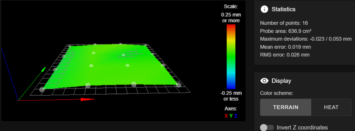
@fcwilt My first post has all the data. I just ran G32 again and this is the result.
Leadscrew adjustments made: 0.048 0.048 0.060, points used 3, (mean, deviation) before (0.052, 0.006) after (-0.000, 0.000)
16 points probed, min error -0.080, max error 0.108, mean 0.023, deviation 0.050
Height map saved to file 0:/sys/heightmap.csv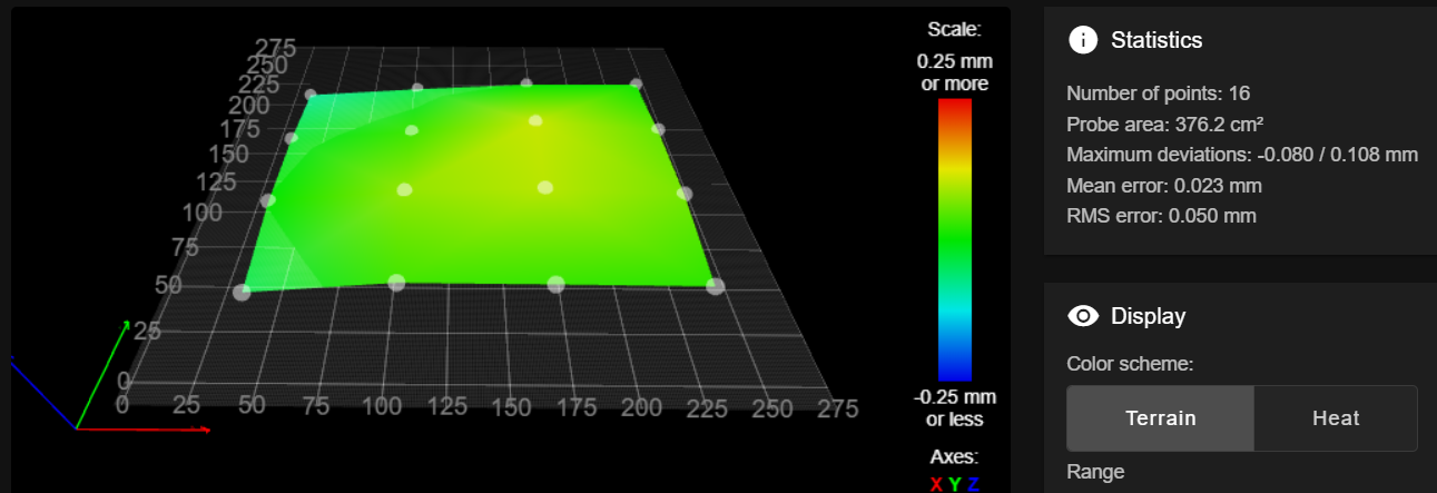
-
@stephen6309 said in Euclid probe and Z=0 datum:
G30 S-2 sets Z0 where the probe triggered. Probes don't trigger the same distance when the nozzle hits the bed, unless the hotend triggers the probe.
S-2 sets the Z offset of the current tool. There is no reason to do that when there is only one tool as the relationship of the tool to the nozzle is fixed.
G30 alone sets the Z axis position to whatever the Z probe Z Trigger Height parameter is. This is intended to insure the Z=0 position of the tip of the nozzle is correct. If the Z Trigger Height parameter is wrong then Z=0 will be off.
Frederick
-
@dhusolo said in Euclid probe and Z=0 datum:
@fcwilt My first post has all the data. I just ran G32 again and this is the result.
Leadscrew adjustments made: 0.048 0.048 0.060, points used 3, (mean, deviation) before (0.052, 0.006) after (-0.000, 0.000)
16 points probed, min error -0.080, max error 0.108, mean 0.023, deviation 0.050
Height map saved to file 0:/sys/heightmap.csv
Aside from not using very many points that heightmap looks OK.
Are you using the left, front grid point to set the Z=0 Datum?
Frederick
-
@fcwilt No I use bed center for Z=0 Datum. That's the way I've always done it.
-
@dhusolo said in Euclid probe and Z=0 datum:
@fcwilt No I use bed center for Z=0 Datum. That's the way I've always done it.
That's fine - that is what I do.
Try specifying a 3x3 grid or a 5x5 grid. The goal is to have the XY position of the center grid point match the XY position used for setting the Z=0 Datum.
If all is good the center most point should be reported as 0 deviation.
Frederick
-
@fcwilt I went with a 5x5 grid and this is the result
Leadscrew adjustments made: -0.197 -0.156 -0.063, points used 3, (mean, deviation) before (-0.142, 0.055) after (0.000, 0.000)
Warning: the height map has a substantial Z offset. Suggest use Z-probe to establish Z=0 datum, then re-probe the mesh.
25 points probed, min error -0.242, max error -0.005, mean -0.139, deviation 0.059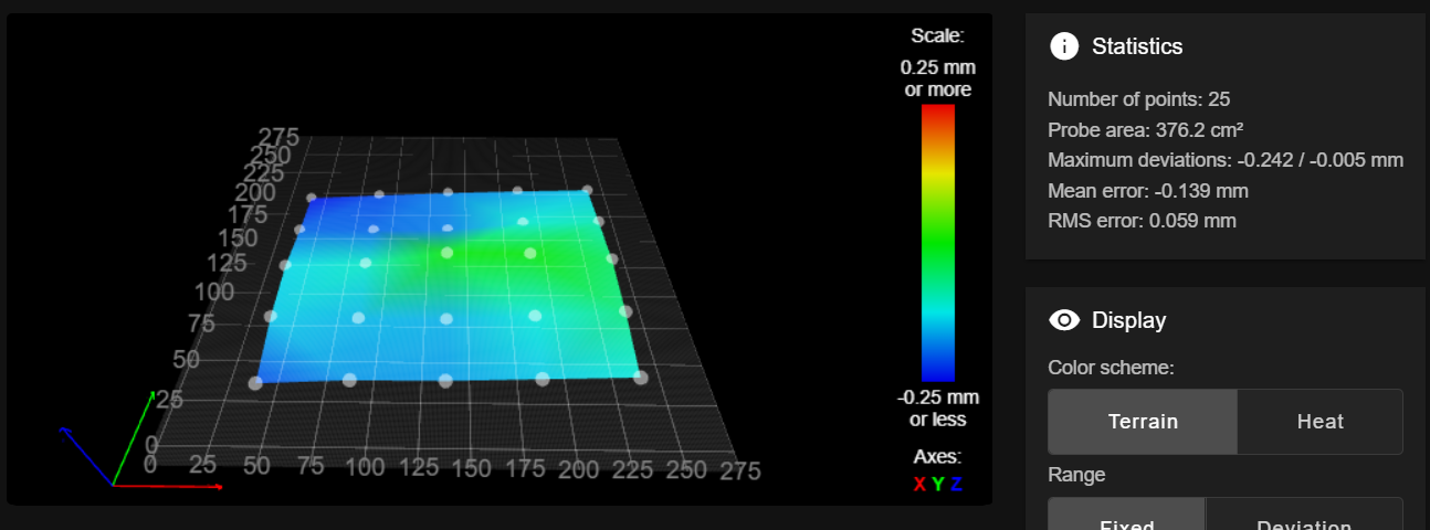
-
Did you determine the XY position of the center point of the grid and use that as the probe XY position when doing the G30 before creating the height map?
Remember when setting the XY position of the probe you have to take into account the XY offsets of the probe.
Frederick
-
@dhusolo Did you get this sorted out ?
-
I usually recommend that the Z point be taken at the geometric center of the 3 kinematic mounts or Z-screws. that point should not really move- everything tips through this point.
-
I seem to get better results with 4 point bedleveling than with 3, that is why the example macros are with 4.
-
Verify that your Z probe trigger point is right. That might throw you off too. Lots of ways to measure this, but I will hold off on your reply.
-
Rememer that sag in the gantry will show up in the terrain map as high points. Its hard to say from the screens shots, but your X rails might be a hair out. You should decide if its worth fussing with.
The folks here and on the Euclid and RC discord are very helpful. We'll get you sorted.
sinneD
-
-
@sinned6915 When I try 4 it gives me an error stating I'm unable to do 4 point leveling because I have 3 lead screws defined.
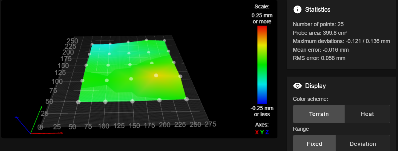
I switched back to a super pinda. and the mesh looks similar to the last one I posted 2 days ago. I'm going to take a step back and look at the frame and motion mechanics. I think something else might be contributing to this or my bed is really that bed.
-
@dhusolo I only have 3 leadscrews also. I probe 4 points that are symmetric in proportion to the shape of my bed.
This is the code I currently run :
; *********************************************************** ; bed4point.g ; *********************************************************** ; probe is -16.4 in X -29.4 in Y bed is 290 in X 325 in Y ; adjust coords so that probe hits symmetric points on bed and avoids dock ; echo move.axes[2].machinePosition ; echo "Running bed4point.g" G90 G30 X145 Y145.0 F600.0 ; home Z G30 P0 X17.0 Y30.0 F9000.0 Z-99999 ; probe front left PEI G30 P1 X17.0 Y265.0 F9000.0 Z-99999 ; probe back left PEI G30 P2 X278.0 Y265.0 F9000.0 Z-99999 ; probe back right PEI G30 P3 X278.0 Y30.0 F9000.0 Z-99999 S3 ; probe near front right leadscrew and calibrate 3 motors PEI ; echo "bed4point.g complete" -
@sinned6915 Ah ok i see what I did wrong. You have 4 G30 coordinates to probe but you still use S3 to define you have 3 leadscrews.
-
@dhusolo glad that helped.
whenever you decide to go back to Euclid, we are here for your if yo need help.
I think you will be well served by both the SuperPinda and the Euclid. -
@sinned6915 Ok so I think the problem was my lead screws. My teflon coated lead screws arrived today and it's more manageable.
Railcore 250zl bed
Granted not as good as my printer with the Railcore 300zl bed and Super Pinda
but it's better than what it was.