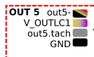
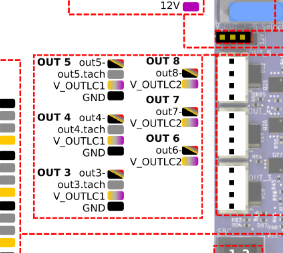
6XD Out 3 4 5
-
This post is deleted! -
Yes Out 3 4 5
Jumper is toward the side of the board where it says "VIN". I guess it should output my 24V IN voltage. -
@herve_smith said in 6XD Out 3 4 5:
The jumpers on the silkscreen say " V Out 3-5" on the left most jumper but the diagram lists it as "out 4-6" which conflicts with the silkscreen
Thanks for pointing this out. I have just fixed the labelling issue with the wiring diagram.
@HighFreq yes if its towards the VIN it will connect VIN to V_OUTLC1 on those headers
Where are you measuring 3.3V? possibly the tacho pins?
-
@t3p3tony between ground and lc_out (first and third pin from down).
Same with gound and vout, first and fourth pin.None of them outputs 24V (my Vin).
-
@highfreq the way you describe the pins does not fit with the wiring diagram (depending which way we describe as up and down.)

-
@t3p3tony counting from the bottm, first is ground. So i expect 24V (my Vin) between ground (firt from bottom) and third or fourth pin. Correct?
Neither V_OUTLC1 or out5- put out 24 Volts. All i get is 3.3V
Where should i get 24V?
I tried between out5 and v_outlc1 too and i get 0 and 3.3V -
@highfreq 24V should be on V_OUTLC1. Test on your input terminals and the jumper as well, maybe there is an issue with the jumper.
-
@t3p3tony Should be between V_OUTLC1 and ground or between V_OUTLC1 and out5?
-
V_OUTLC1 and GND. Also between V_OUTLC1 and out5- when out5- is turned on.
-
@t3p3tony i only get 0 or 3.3V between V_OUTLC1 and out5.
0 when off ad 3.3V when on.
Do you have a chance to test to see if there is a problem on the 6XD? -
@highfreq please test between ground and VIN on the input terminal and between ground and the center pin of the 3 pin jumper It may be that the fuse has blown
-
@t3p3tony will test tomorrow as soon as i get in office, thanks for your help.
-
@t3p3tony Fuse is ok, can you please check if there is an error on the board?
The OUTLC2 works at 25V as expected, while OUTLC1 is at 3.3V.I think there is some error on the board between the jumper and the OUTLC1.
It works if i use out5.tach so i guess pin V_OUTLC1 and out5.tach are inverted.
There is 25 Volts on out5.tach instead of V_OUTLC1.
Please let me know.
-
@highfreq Ahh right, now I understand what the issue is. Apologies it took so long: the wiring diagram had an error in it, I have fixed that now:

Thanks for your patience and for bearing with me in working out what was wrong.
-
@t3p3tony Ok great, thanks.
Corrado