CUSTOM KINEMATICS
-
Hello everybody! I'm building my own 3D printing robot. I will use RRF and I'm new in this world.
So my design is pretty simple, 3xNEMA23 with TB6600. One for rotatory body, other for Z axis and the last one for radial distance. Its something like a prismatic robot + SCARA.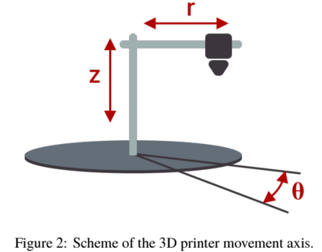
My question is: Can use one of the existing kinematics or I should use M669 for a "Robot Printer"?
I have already calculated the H-D parameters for it and I obtained the following table:Art Theta d a Alpha 1 q1 0 0 0 ; base with rotation (max 90deg) 2 0 d1 0 0 ; the Z linear axis (max 20mm) 3 0 0 d2 pi/2 ; the r linear axis (max 200mm)The first one is the base.
With these parameters, how can I define the M669 command? Should I put variables or a numerical value.I will apreciate any advice or help.
Thaks everybody.
-
@xxjrushmanxx Is this any help https://docs.duet3d.com/en/User_manual/Machine_configuration/Configuration_Polar ?
Duet WiFi hardware designer and firmware engineer
Please do not ask me for Duet support via PM or email, use the forum
http://www.escher3d.com, https://miscsolutions.wordpress.com -
Correction:"One for rotatory base" => Rotation is not in the bed, is in the body. Like a crane for buildings.
Your link is for a turntable bed and not for the body. Can I use it anyway?Isn't the same angle in 2 cases, or yes? Because the centers are not in the same point. In my case the center = origin of the sistem/body. ( At the polar center of bed ≠ center of the body)
How I can change the angular axis from bed to body?
Thaks for your fast answer, I really need it!!! -
@xxjrushmanxx in polar kinematics it doesn't matter whether the bed rotates or the gantry rotates, it's all relative. The gantry rotating one way is equivalent to the bed rotating the other way.
Duet WiFi hardware designer and firmware engineer
Please do not ask me for Duet support via PM or email, use the forum
http://www.escher3d.com, https://miscsolutions.wordpress.com -
@dc42
Okey, to begin with a big thanks for your attention!!!My next questions about polar kinematics are:
-
How I can define the rotative-origin of the rotative axis (≈center of the bed)?
It's my biggest mystery... In polar we have max and min radius, and the center is in the middle.
But I have my min_rad at 10cm from my real rotatory center and max_rad at 30cm from it. My case is a donut work zone (or just part of it, 90deg for start ) -
In the rotative axie, where do we use mm and where degrees?
In config.h there is only mm (ej: M566, M92) so I can understand that in M208 we should to write Y__mm instead of Y__degree.
But at the homing files we are working at degrees.
So I need to calculate mm from degrees? How I can take step/mm for rotative axie? -
If I use external drivers, should I use M350, M906, M84?
-
There is core files I should to check exept homing files?
Waiting for a response
Sincerely
Alexander
-