Compatibility 1HCL motor encoder closed loop
-
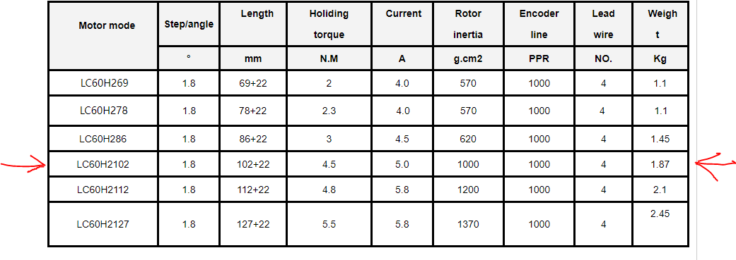
Hello, reading the characteristics it seems to me that the 1HCL expansion is compatible with this motor :
the doubt is on 1000PPR encoder
The goal is to check for any engine position alarms and improve the wiring.
I would like to try using this new expansion on a printer with 7 engines.
I wouldn't want any nasty surprises given the cost of the components.
Could someone please confirm?
Many thanks to all and happy holidays -
@3Dream, 1000 PPR is typical for a stepper motor with optical encoder. So that motor appears to be suitable to me.
By using all four quadrature transitions we can get 4000 counts/rev resolution from a 1000 PPR encoder, although the 4 sub-counts may be less evenly spaced.
Duet WiFi hardware designer and firmware engineer
Please do not ask me for Duet support via PM or email, use the forum
http://www.escher3d.com, https://miscsolutions.wordpress.com -
@dc42 Many thanks
I proceed to purchase -
@dc42
Good morning,
the configuration of the machine is going well, and almost everything works.
I have a problem with the OUT0 and OUT 1 outputs of the 1HCL.
The outputs work fine when used with V fused but I can't get them to work when used with V brake. I have 24V input power to the 1HCL but I can't get 24V output.
I'm trying to use it to power a fan.
The CAN 56.0 board refers to the X axis motor of the machine
This is the configuration in config.g;Ventole
M950 F0 C"56.out1" Q250
M106 P0 C"Part"Thank you very much for helping
-
@3Dream please provide a photo of your wiring showing how you have provided the VBRAKE supply to the EXP1HCL board.
Duet WiFi hardware designer and firmware engineer
Please do not ask me for Duet support via PM or email, use the forum
http://www.escher3d.com, https://miscsolutions.wordpress.com -
@dc42
The 24V that I send to the 1HCL V_Brake input is the same that I use to power the motherboard and all the 24V users (pump, fixed fans) -
@3Dream you cold check the two fuses on the 1HCL board. One of them is for the VBRAKE input.
Duet WiFi hardware designer and firmware engineer
Please do not ask me for Duet support via PM or email, use the forum
http://www.escher3d.com, https://miscsolutions.wordpress.com -
@dc42 the 24V fuse had blown. I replaced it but the out 1 output smoked when the fan was turned on. I do not understand..
-
@3Dream I suspect the fan is either faulty or was connected with reverse polarity.
Duet WiFi hardware designer and firmware engineer
Please do not ask me for Duet support via PM or email, use the forum
http://www.escher3d.com, https://miscsolutions.wordpress.com -
@dc42
Good morning,
i'm having trouble using my engines on 1HCL boards.
I have used this configuration of motors / screws / guides / structure weight on other machines with external drive and 1XD cards without problems.
The printer is very large.
After tuning example ( M569.6 P50.0 V1 )
On the 4 Z-axis motors (5mm pitch ball screws)
I get example:
Driver 50.0 basic tuning succeeded, measured backlash 0.067 step
But on X Y axes where I use 15mm pitch ball screws
I get example:
Error: Driver 54.0 basic tuning failed, measured backlash (0.237 step) is too high
Warning: Driver 54.0 warning: tuning/calibration failed
I can only reduce the backlash error by disconnecting the screws from the motors.
Can I solve it in some other way?
I installed version 3.5 and tried to use closed loop auto tune without success.
Is there an instruction manual explaining how to use it and where is the data saved?
I can't figure out how to use it
Thank you
David -
@3Dream what motor current have you configured, and what is the rated current of the motor? Increasing motor current will reduce backlash.
Firmware 3.5 for the EXP1HCL is better than 3.4.x, and the current 3.5beta2 release of EXP1HCL firmware is compatible with 3.4.x firmware on the main board. However, some of the M569.1 configuration parameters have changed in 3.5. See the GCodes wiki page for details.
Duet WiFi hardware designer and firmware engineer
Please do not ask me for Duet support via PM or email, use the forum
http://www.escher3d.com, https://miscsolutions.wordpress.com -
@dc42
i'm using 5000 which is the maximum i think right?
M906 X5000 Y5000:5000
-
@3Dream motor rated current is usually specified for both phases energised, and microstepping drivers only energise one phase fully at a time. So it's safe to increase motor current somewhat when the motor is not at standstill. You could try increasing it to 6000 just before tuning, and reduce back to 5000 immediately afterwards. You could use M913 to do this, as it appears to allow greater than 100% of normal current.
The maximum accepted backlash in firmware 3.5 is 0.22 full steps so you are not far off.
Duet WiFi hardware designer and firmware engineer
Please do not ask me for Duet support via PM or email, use the forum
http://www.escher3d.com, https://miscsolutions.wordpress.com -
@dc42
I tried to bring the value to 6000 but the result doesn't change, maybe it gets worse.Z motors:
Driver 50.0 basic tuning succeeded, measured backlash 0.068 step
Driver 51.0 basic tuning succeeded, measured backlash 0.082 step
Driver 52.0 basic tuning succeeded, measured backlash 0.072 step
Driver 53.0 basic tuning succeeded, measured backlash 0.078 stepY motors:
Error: Driver 54.0 basic tuning failed, measured backlash (0.241 step) is too high
Warning: Driver 54.0 warning: tuning/calibration failed
Warning: Driver 55.0 basic tuning succeeded but measured backlash (0.218 step) is highX motors:
Warning: Driver 56.0 basic tuning succeeded but measured backlash (0.170 step) is high
I am attaching my config referring to the motors.
Tell me if you see any errors please.;Impostazione motori
M569 P50.0 D4 S0; Senso rotazione motori Z0 Post SX
M569.1 P50.0 T2 C1000 S200 R100 I0 D0 ; Configure the 1HCL board at CAN address 50 with a quadrature encoder on the motor shaft that has 5 steps per motor full step.
M569 P51.0 D4 S0; Senso rotazione motori Z1 Ant SX
M569.1 P51.0 T2 C1000 S200 R100 I0 D0 ; Configure the 1HCL board at CAN address 50 with a quadrature encoder on the motor shaft that has 5 steps per motor full step.
M569 P52.0 D4 S0; Senso rotazione motori Z2 Ant DX
M569.1 P52.0 T2 C1000 S200 R100 I0 D0 ; Configure the 1HCL board at CAN address 50 with a quadrature encoder on the motor shaft that has 5 steps per motor full step.
M569 P53.0 D4 S0; Senso rotazione motori Z3 Post DX
M569.1 P53.0 T2 C1000 S200 R100 I0 D0 ; Configure the 1HCL board at CAN address 50 with a quadrature encoder on the motor shaft that has 5 steps per motor full step.
M569 P54.0 D4 S1 ; Senso rotazione motori Y1 SX
M569.1 P54.0 T2 C1000 S200 R100 I0 D0 ; Configure the 1HCL board at CAN address 50 with a quadrature encoder on the motor shaft that has 5 steps per motor full step.
M569 P55.0 D4 S1 ; Senso rotazione motori Y2 DX
M569.1 P55.0 T2 C1000 S200 R100 I0 D0 ; Configure the 1HCL board at CAN address 50 with a quadrature encoder on the motor shaft that has 5 steps per motor full step.
M569 P56.0 D4 S1 ; Senso rotazione motori X
M569.1 P56.0 T2 C1000 S200 R100 I0 D0 ; Configure the 1HCL board at CAN address 50 with a quadrature encoder on the motor shaft that has 5 steps per motor full step.
M569 P0.0 S0
M584 X56.0 Y54.0:55.0 Z50.0:51.0:52.0:53.0 E0.0 P3; Assegnazione motori
M917 X100 Y100 Z100 ; Set the closed loop axes to have a holding current of zero
M350 X128 Y128 I0 ; set steps/mm to 64 to make full use of the encoder resolution
M350 Z32 I0 ; set steps/mm to 32 to make full use of the encoder resolution
M350 E16 I0 ; set steps/mm to 16 to make full use of the encoder resolution
M92 X1600 Y1600 Z1280 E274; Step giro motori
M566 X500 Y500 Z400 E300; Jerk motori
M203 X10000 Y10000 Z1500 E3000; Velocita motori
M201 X1000 Y1000 Z150 E2000; Accelerazione motori
M906 X5000 Y5000 Z4500 E2300 I50; corrente motori
M84 S30
M572 D0 S0.05
;Corse macchina
M208 X0 Y0 Z0 S1; Posizione corsa minima
M208 X1490 Y1450 Z998.2 S0; Posizione corsa massima era 1031.5
;Finecorsa
M574 X1 S1 P"56.io0.in"
M574 Y1 S1 P"54.io0.in+55.io0.in" ; doppio finecorsa microswitch su assi Y SU 1XD 46.io0.in
M574 Z2 S1 P"50.io0.in+51.io0.in+52.io0.in+53.io0.in" ; quadruplo finecorsa proximity su assi Z SU 1XD era !53.io0.in
;Posizione proximity e bed levelling
M558 P5 C"^!io0.in" H8 R1 F120 T10000
G31 P600 X0 Y55 Z1.1; era Z
M557 X5:1490 Y60:1490 S495:476 -
@dc42
Hello DC42,
would it be possible to connect an accelerometer like Adafruit LIS3DH to a 1HCL?
On the encoder connector I connected only 4 wires GND, 5V, A input and B input.
Only SPI_SCK would be missing. Can I use CS or CCK?
Thank you -
@3Dream in principle it would be possible to use an encoder connected to the ribbon cable connector, using the CS pin normally used for a magnetic encoder as the CS pin for the accelerometer, and using the N input on the other connector for the INT pin. However, the expansion board firmware does not yet support SPI-connected accelerometers. I could try enabling that in the next 3.5breta release.
Duet WiFi hardware designer and firmware engineer
Please do not ask me for Duet support via PM or email, use the forum
http://www.escher3d.com, https://miscsolutions.wordpress.com -
@dc42
ok thanks, when is the next 3.5 release expected?
Currently if I carried a cable from the head/accelerometer to the motherboard I would have a cable about 7 meters long; Do you think it's ok or are there too many problems?
Thanks again and sorry for the many questions -
@3Dream I think a 7m cable would be too long. Another possibility would be to use a SAMMYC21 board to connect the accelerometer. For non-commercial use a RP2040 + CAN-FD transceiver chip could also be used to host an accelerometer.
Are you using the EXP1HCL board to drive the extruder motor?
Duet WiFi hardware designer and firmware engineer
Please do not ask me for Duet support via PM or email, use the forum
http://www.escher3d.com, https://miscsolutions.wordpress.com -
@dc42 Good evening
Indeed the 7 meter cable does not work, it recognizes Adafruit LIS3DH but creates problems.
So using one of these two systems as an interface could I connect to the EXP1HCL CAN with the Adafruit LIS3DH accelerometer?
Could you give me a link to understand which one to choose and how to connect it?
I'm not using the EXP1HCL board to drive the extruder motor but I drive it directly with the motherboard driver.
However the last EXP1HCL board of the can line is connected to the X axis and is located near the extruder. Approximately 1.5 meter cable. -
@3Dream are you using the io0 and/or io1 connector on that 1HCL board?
Duet WiFi hardware designer and firmware engineer
Please do not ask me for Duet support via PM or email, use the forum
http://www.escher3d.com, https://miscsolutions.wordpress.com