Toolboard failure?
-
I recently changed my hotend to a revo six. I changed the thermistor configuration based on this forum as follows.
M308 S0 P"temp0" Y"thermistor" T100000 B4725 C7.06e-08F
The first couple prints were not very satisfactory so I started some basic tuning. While testing the max extrusion rate at different temperatures twice the temperature went to 2000C. I reset the system and it returned to a reasonable temperature. Later the temperature just started climbing from the 210 setting. I set the temperature to zero and it did start falling but started to level out around 170C. I disconnected the thermistor and the temperature dropped to ~39C. I connected a known good thermistor and the indicated temperature returned to ~160 with the thermistor at room temperature. With no thermistor connected the toolboard reports 39.2C.
My conclusion is the toolboard has failed but on the chance there is something else wrong I am posting here.
Here are the results of Diagnostics
M122
=== Diagnostics ===
RepRapFirmware for Duet 3 MB6HC version 3.4.1 (2022-06-01 21:09:01) running on Duet 3 MB6HC v1.01 or later (SBC mode)
Board ID: 08DJM-956L2-G43S8-6J1D6-3S86R-KA3YF
Used output buffers: 1 of 40 (12 max)
=== RTOS ===
Static ram: 151000
Dynamic ram: 66164 of which 28 recycled
Never used RAM 133408, free system stack 137 words
Tasks: SBC(ready,0.6%,466) HEAT(notifyWait,0.0%,321) Move(notifyWait,0.0%,267) CanReceiv(notifyWait,0.0%,772) CanSender(notifyWait,0.0%,356) CanClock(delaying,0.0%,339) TMC(notifyWait,7.9%,58) MAIN(running,91.5%,923) IDLE(ready,0.1%,30), total 100.0%
Owned mutexes: HTTP(MAIN)
=== Platform ===
Last reset 00:24:38 ago, cause: software
Last software reset at 2023-03-17 10:02, reason: User, GCodes spinning, available RAM 133264, slot 0
Software reset code 0x0003 HFSR 0x00000000 CFSR 0x00000000 ICSR 0x00400000 BFAR 0x00000000 SP 0x00000000 Task SBC Freestk 0 n/a
Error status: 0x00
Step timer max interval 135
MCU temperature: min 33.8, current 34.1, max 34.4
Supply voltage: min 23.8, current 23.9, max 23.9, under voltage events: 0, over voltage events: 0, power good: yes
12V rail voltage: min 11.8, current 11.9, max 11.9, under voltage events: 0
Heap OK, handles allocated/used 0/0, heap memory allocated/used/recyclable 0/0/0, gc cycles 0
Events: 0 queued, 0 completed
Driver 0: standstill, SG min 0, mspos 40, reads 51000, writes 19 timeouts 0
Driver 1: standstill, SG min 0, mspos 680, reads 51001, writes 19 timeouts 0
Driver 2: standstill, SG min 0, mspos 312, reads 51001, writes 19 timeouts 0
Driver 3: standstill, SG min 0, mspos 312, reads 51001, writes 19 timeouts 0
Driver 4: standstill, SG min 0, mspos 312, reads 51001, writes 19 timeouts 0
Driver 5: standstill, SG min 0, mspos 8, reads 51009, writes 11 timeouts 0
Date/time: 2023-03-17 10:27:33
Slowest loop: 32.67ms; fastest: 0.04ms
=== Storage ===
Free file entries: 10
SD card 0 not detected, interface speed: 37.5MBytes/sec
SD card longest read time 0.0ms, write time 0.0ms, max retries 0
=== Move ===
DMs created 125, segments created 3, maxWait 16511ms, bed compensation in use: none, comp offset 0.000
=== MainDDARing ===
Scheduled moves 11, completed 11, hiccups 0, stepErrors 0, LaErrors 0, Underruns [0, 0, 0], CDDA state -1
=== AuxDDARing ===
Scheduled moves 0, completed 0, hiccups 0, stepErrors 0, LaErrors 0, Underruns [0, 0, 0], CDDA state -1
=== Heat ===
Bed heaters 0 -1 -1 -1 -1 -1 -1 -1 -1 -1 -1 -1, chamber heaters -1 -1 -1 -1, ordering errs 0
Heater 1 is on, I-accum = 0.0
=== GCodes ===
Segments left: 0
Movement lock held by null
HTTP* is doing "M122" in state(s) 0
Telnet is idle in state(s) 0
File is idle in state(s) 0
USB is idle in state(s) 0
Aux is idle in state(s) 0
Trigger* is idle in state(s) 0
Queue is idle in state(s) 0
LCD is idle in state(s) 0
SBC is idle in state(s) 0
Daemon is idle in state(s) 0
Aux2 is idle in state(s) 0
Autopause is idle in state(s) 0
Code queue is empty
=== CAN ===
Messages queued 13329, received 29600, lost 0, boc 0
Longest wait 5ms for reply type 6024, peak Tx sync delay 244, free buffers 50 (min 49), ts 7394/7393/0
Tx timeouts 0,0,0,0,0,0
=== SBC interface ===
Transfer state: 5, failed transfers: 0, checksum errors: 0
RX/TX seq numbers: 58635/58635
SPI underruns 0, overruns 0
State: 5, disconnects: 0, timeouts: 0 total, 0 by SBC, IAP RAM available 0x2b880
Buffer RX/TX: 0/0-0, open files: 0
=== Duet Control Server ===
Duet Control Server v3.4.1
Code buffer space: 4096
Configured SPI speed: 8000000Hz, TfrRdy pin glitches: 0
Full transfers per second: 39.71, max time between full transfers: 128.2ms, max pin wait times: 59.8ms/27.1ms
Codes per second: 0.08
Maximum length of RX/TX data transfers: 3044/904 -
@wifibeagle I believe the thermistor series resistor has been damaged by static discharge. This can unfortunately happen because of the small size of that resistor. To avoid static discharge in future you should ground hot end metalwork, either directly to the ground side of the VIN power input, or via a resistor (e.g. 100Kohms or 1Mohm) to any Duet ground connection.
The tool board has two temperature inputs, so to avoid having to replace the resistor you can use the second one.
Duet WiFi hardware designer and firmware engineer
Please do not ask me for Duet support via PM or email, use the forum
http://www.escher3d.com, https://miscsolutions.wordpress.com -
@dc42 After changing to temp1 the room temperature reading is now about 244.4C. So it appears the second input also has a problem. Testing with a different thermistor is not as easy as I only have the one tiny plug to fit temp1. It looks like the resistors on the toolboard are the tiny 402 size. I do have a microscope but it would be challenging to replace something so small. Which resistors would need to be changed?
My hot end is installed in a Precision Piezo Orion which does insulate it from the rest of the machine. I'm still trying to decide how to ground the Revo hot end.
-
@wifibeagle if both temperature inputs give incorrect readings then the problem is somewhere else.
Please run M122 B# where # is the CAN address of the tool board, to get a diagnostic report for the tool board.
Duet WiFi hardware designer and firmware engineer
Please do not ask me for Duet support via PM or email, use the forum
http://www.escher3d.com, https://miscsolutions.wordpress.com -
@dc42 Here's the M122
m122 B121
Diagnostics for board 121:
Duet TOOL1LC rev 1.0 or earlier firmware version 3.4.1 (2022-06-01 21:16:39)
Bootloader ID: not available
All averaging filters OK
Never used RAM 3512, free system stack 80 words
Tasks: Move(notifyWait,0.0%,153) HEAT(notifyWait,0.4%,95) CanAsync(notifyWait,0.0%,61) CanRecv(notifyWait,0.0%,76) CanClock(notifyWait,0.0%,65) TMC(notifyWait,3.0%,57) MAIN(running,91.7%,351) IDLE(ready,0.0%,40) AIN(delaying,4.9%,142), total 100.0%
Last reset 01:10:53 ago, cause: software
Last software reset at 2021-03-11 09:54, reason: HardFault, available RAM 3936, slot 0
Software reset code 0x0060 ICSR 0x00000003 SP 0x20002f60 Task MAIN Freestk 746 ok
Stack: 00000001 00000002 2000332c 00000000 41000000 a5a5a5a5 00017aba 61000000 a5a5a5a5 2000332c 20006db8 a5a5a5a5 a5a5a5a5 4b07e7d4 a5a5a5a5 20003398 00000001 200033d8 a5a5a5a5 00017bbb a5a5a5a5 a5a5a5a5 a5a5a5a5 a5a5a5a5 20000ddc 00000001 200020b4
Driver 0: pos 0, 420.0 steps/mm,standstill, SG min 0, read errors 0, write errors 1, ifcnt 25, reads 29552, writes 12, timeouts 0, DMA errors 0, CC errors 0, steps req 0 done 0
Moves scheduled 0, completed 0, in progress 0, hiccups 0, step errors 0, maxPrep 0, maxOverdue 0, maxInc 0, mcErrs 0, gcmErrs 0
Peak sync jitter 5/10, peak Rx sync delay 213, resyncs 0/0, no step interrupt scheduled
VIN voltage: min 24.1, current 24.2, max 24.2
MCU temperature: min 32.6C, current 33.8C, max 33.9C
Last sensors broadcast 0x00000002 found 1 221 ticks ago, 0 ordering errs, loop time 1
CAN messages queued 85068, send timeouts 0, received 38296, lost 0, free buffers 37, min 37, error reg 0
dup 0, oos 0/0/0/0, bm 0, wbm 0, rxMotionDelay 0
Accelerometer: none -
@wifibeagle thanks. I suspect that both the damage to the temperature input and the unexpected reset were caused by static discharge between the hot end metalwork and the thermistor input. To avoid this in future, ground the hot end metalwork, either directly to the VIN ground terminal, or through a resistor (e.g. 100K) to any Duet ground connection. The reason for the resistor is to protect the Duet if you get a short between a heater connection and the hot end metalwork.
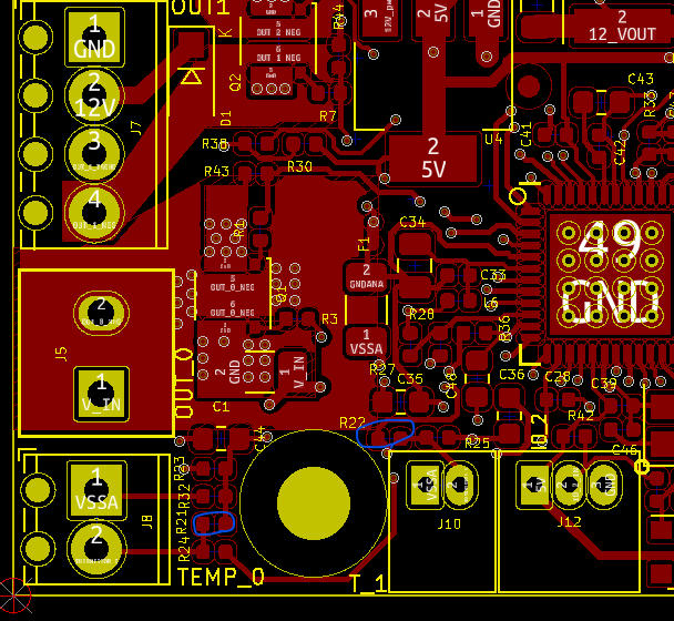
The resistors that probably need to be replaced are R21 and R22. The specification is 2.2K 0.1% tolerance size 0402, however 1% tolerance should be OK if you are not using PT1000 sensors. Instructions for replacing them are similar to the ones I gave for the Duet 3 Mini here https://forum.duet3d.com/post/310657. This is where they are on the version 1.0 tool board:
I suggest you test the resistors in-situ with a multimeter first, to check that it where the fault lies.
Duet WiFi hardware designer and firmware engineer
Please do not ask me for Duet support via PM or email, use the forum
http://www.escher3d.com, https://miscsolutions.wordpress.com -
@dc42 R21 measures about 200K, R22 1890 Ohms. The resistor appears to be the issue with T0. R22 is close enough to 2.2K that T1 looks like a different problem. I will order some resistors and try replacing R21.
Meanwhile I have ordered a replacement toolboard and will ground the hotend before powering any tooboard.
Thanks for your help.
John
-
@wifibeagle for T1 it could be that the 10K resistor R25 has failed, or perhaps it is a different problem e.g. bad crimp connection. For T0 it definitely sounds as though R21 has failed, which could be caused by ESD or by a short between the temperature input and the hot end heater.
Duet WiFi hardware designer and firmware engineer
Please do not ask me for Duet support via PM or email, use the forum
http://www.escher3d.com, https://miscsolutions.wordpress.com -
@dc42 R25 measures about 3.6K ohms which seems close enough in circuit to suggest it is functional. So the T1 issue is still unknown. I will look for possible external problems as you suggested.
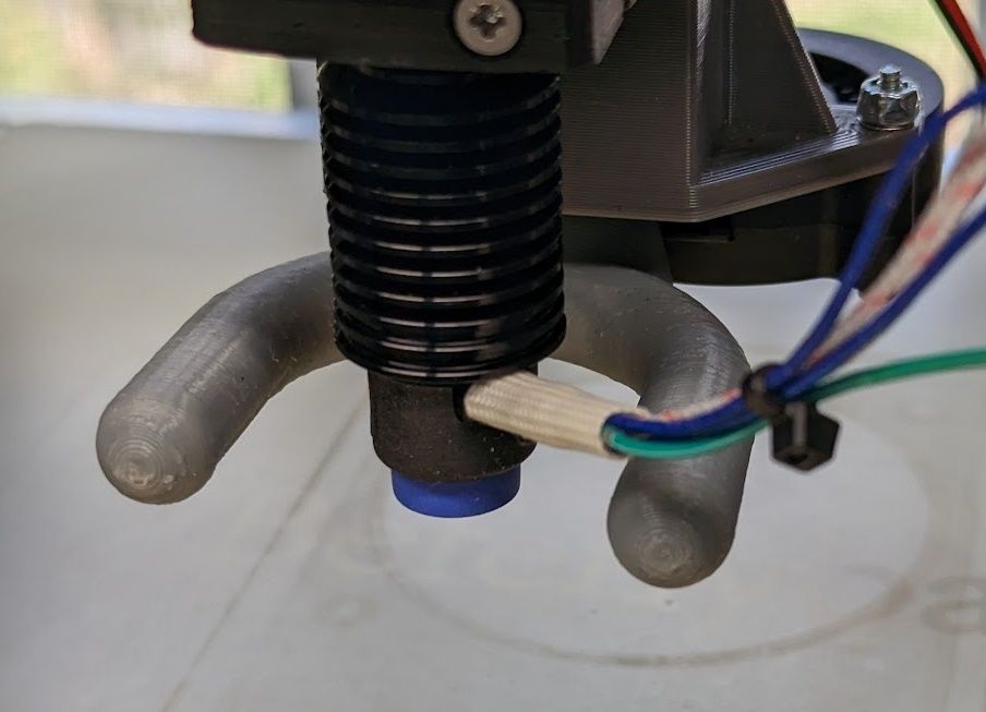
I have ordered a R1.3 toolboard due today. I see the mounting holes are grounded through a 100K resistor. I have found a good way to add a ground wire to the Revo heater block by sliding a male Dupont connector between the wires and the metal strain relief. I will connect it to one of the mounting screws. I also plan to replace the plastic mounting standoffs with metal ones to ground the board to the aluminum mount for the extruder. I verified there is a good connection through the heater core to the nozzle. I'm including a couple pictures of the grounding in case someone stumbles upon this post with a similar issue.
Thank you for your help and prompt response.
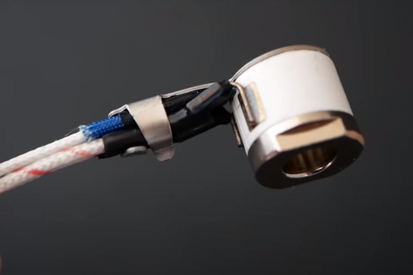
This image was captured from cnckitchen's excellent review of the Revo (https://www.cnckitchen.com/blog/e3d-rapidchange-revo-review)
-
@wifibeagle bear in mind that the version 1.3 tool boards has the mounting holes in different places. There is a rev 1.2a that has them in the original locations.
Duet WiFi hardware designer and firmware engineer
Please do not ask me for Duet support via PM or email, use the forum
http://www.escher3d.com, https://miscsolutions.wordpress.com -
@dc42 I selected r1. 3 because I may change to the hemera xs knowing the mount spacing is different. I have already added the new mounting holes to my bracket. The grounding through the mounting is also a bonus. I'll have to modify the wiring connections either way.