Inability to move Axis
-
X,Y and Z will not move whatsoever , unless I perform a emergency stop in which case X will strangley move to the right. My Z axis uses 3 motors each with there own driver. I believe I have written this into the G code correctly. Any help or advice would be greatly appreciated , Thank You.
-
@900turbo Your drive mapping for Z is incorrect, you haven't specified driver 0.2 with M569 (it's best to specify all used drivers with their own M569), and you're using the same drive for Z and E! It should be in the form:
M584 X0.5 Y0.4 Z0.1:0.2:0.3 E0.6
This may not be correct for your board. Which Duet board is it? Does it have 6 drivers?Ian
Bed-slinger - Mini5+ WiFi/1LC | RRP Fisher v1 - D2 WiFi | Polargraph - D2 WiFi | TronXY X5S - 6HC/Roto | CNC router - 6HC | Tractus3D T1250 - D2 Eth
-
@droftarts Im using a Duet MB 6XD so 6 Driver ports and Im also using a 1LC which the extruder motor is wired into. The printer is Core XY.
-
@900turbo Motors driver should be mapped to the CAN address of the board, then the driver. CAN address 0 is the mainboard, so
M584 X0.5is the 6XD driver 5. So the extruder needs to be mapped to the 1LC. As there's only one driver on a 1LC, driver 0, it should be something likeM584 E121.0. CAN addressing also applies to fans, heaters etc. See https://docs.duet3d.com/User_manual/Machine_configuration/CAN_connection#using-can-addressesAlso, you can cut and paste text from DWC into your post, rather than posting pictures. This makes it easier to copy your code and correct it.
Ian
Bed-slinger - Mini5+ WiFi/1LC | RRP Fisher v1 - D2 WiFi | Polargraph - D2 WiFi | TronXY X5S - 6HC/Roto | CNC router - 6HC | Tractus3D T1250 - D2 Eth
-
@900turbo Also, if you are using external drivers (which you are because you have a 6XD), you will almost certainly have to set the pulse timing suitable for your drivers in M569, for each drive. If you post a link to the drivers you are using, we can suggest some settings. See https://docs.duet3d.com/User_manual/Connecting_hardware/Motors_connecting_external#configuring-the-enable-polarity
Also check that your driver is set up to receive step and direction pulses, and that the wiring is correct. See https://docs.duet3d.com/Duet3D_hardware/Duet_3_family/Duet_3_Mainboard_6XD_Hardware_Overview#connecting-external-motor-drivers
Ian
-
@droftarts My other 121 Can adresses have been mapped fine so im not sure why RepRap has done this to the drivers. I will copy and paste everthing I have as I am a bit lost at this point.
-
@900turbo
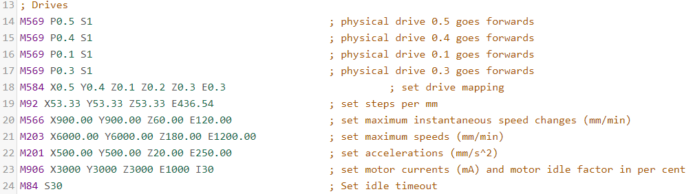
; Drives
M569 P0.5 S1 ; physical drive 0.5 goes forwards
M569 P0.4 S1 ; physical drive 0.4 goes forwards
M569 P0.1 S1 ; physical drive 0.1 goes forwards
M569 P0.3 S1 ; physical drive 0.3 goes forwards
M584 X0.5 Y0.4 Z0.1:0.2:0.3 E0.6
M584 E121.0
M92 X53.33 Y53.33 Z53.33 E436.54 ; set steps per mm
M566 X900.00 Y900.00 Z60.00 E120.00 ; set maximum instantaneous speed changes (mm/min)
M203 X6000.00 Y6000.00 Z180.00 E1200.00 ; set maximum speeds (mm/min)
M201 X500.00 Y500.00 Z20.00 E250.00 ; set accelerations (mm/s^2)
M906 X3000 Y3000 Z3000 E1000 I30 ; set motor currents (mA) and motor idle factor in per cent
M84 S30 ; Set idle timeout -
@droftarts https://oceancontrols.com.au/files/datasheet/lea/smc003_M542_manual.pdf
Here are the External drivers -
@900turbo I also checked the DIP switches on the drivers to make sure they are setup correctly which they are as well as the wiriing that follows the Duet guide.
-
@900turbo Change your M584 commands to one line, this:
M584 X0.5 Y0.4 Z0.1:0.2:0.3 E121.0Taking just the X axis (the others should be the same), the M569 should be something like:
M569 P0.5 S1 R1 T5:5:10:10The P parameter defines the driver number. The S parameter the direction of rotation.
The R parameter defines the driver enable polarity: 0 = active low (default), 1 = active high. Your drivers look like they are active high.
The T parameter, where Taa:bb:cc:dd, defines the minimum driver step pulse width (aa), step pulse interval (bb), direction setup time (cc) and direction hold time (dd), in microseconds. Referring to the driver manual, these are 1.5us, 1.5us, 5us, 5us. These are the fastest timings; to check it's working, I have doubled these to 5us, 5us, 10us, 10us.Note that in the manual it says:
Usually, ENA+ and ENA- are NC (not connected). See “Connector P1 Configurations” for more information.
So if you are still having problems, try disconnecting ENA+ and ENA-. This usually means that the motors are enabled as soon as the drivers are powered.
Ian
Bed-slinger - Mini5+ WiFi/1LC | RRP Fisher v1 - D2 WiFi | Polargraph - D2 WiFi | TronXY X5S - 6HC/Roto | CNC router - 6HC | Tractus3D T1250 - D2 Eth
-
@droftarts I changed the G code to what you suggested and nothing would move then unplugged ENA + and ENA -. I can now control the X and Y axis I still cannot control Z1,2,3. Y seems to hone perfectly cutting out when making contact with the endstop. However X goes the opposite direction to its end stop when asked to hone. Is Z not moving because of how the optical endstops have been configured ?
Thanks for the help so far would be stuck without it. -
@900turbo There are a number of reasons that the X axis might go the wrong way:
- Sending a positive move results in a physical move in the negative direction: change M569 S parameter. If it is S1, change it to S0. If it is S0, change it to S1.
- If it is during homing, the endstops might already be triggered, and the axis is trying to move away from the endstop. Test endstops (check this for Z axis not moving, too), see https://docs.duet3d.com/en/How_to_guides/Commissioning#h-8-check-endstops
- Endstop is defined at the maximum end, but is physically at the minimum end of the axis. Check endstop position on axis.
Without seeing the full config.g and homing files, I can't tell how it is setup at the moment. Please share those, either by uploading them (you can upload .g files, or add ".txt" to the end so they can be opened in the browser) or by copying and pasting the text into your reply. Also send M115 and post the response, so we know what firmware version you are using.
Ian
Bed-slinger - Mini5+ WiFi/1LC | RRP Fisher v1 - D2 WiFi | Polargraph - D2 WiFi | TronXY X5S - 6HC/Roto | CNC router - 6HC | Tractus3D T1250 - D2 Eth
-
-
-
@900turbo Reproducing your config.g and homeall.g here for ease of reference:
; Configuration file for Duet 3 MB 6XD (firmware version 3.3)
; executed by the firmware on start-up
;
; generated by RepRapFirmware Configuration Tool v3.3.16 on Mon Apr 17 2023 13:03:57 GMT+0100 (British Summer Time)

; General preferences
M575 P1 S1 B57600                                  ; enable support for PanelDue
G90                                                ; send absolute coordinates...
M83                                                ; ...but relative extruder moves
M550 P"Duet 3"                                     ; set printer name
M669 K1                                            ; select CoreXY mode

; Drives
M569 P0.5 S1 R1 T5:5:10:10                                    ; physical drive 0.5 goes forwards
M569 P0.4 S1                                       ; physical drive 0.4 goes forwards
M569 P0.1 S1                                       ; physical drive 0.1 goes forwards
M569 P0.3 S1                                       ; physical drive 0.3 goes forwards
M584 X0.5 Y0.4 Z0.1:0.2:0.3 E121.0
M92 X53.33 Y53.33 Z53.33 E436.54                   ; set steps per mm
M566 X900.00 Y900.00 Z60.00 E120.00                ; set maximum instantaneous speed changes (mm/min)
M203 X6000.00 Y6000.00 Z180.00 E1200.00            ; set maximum speeds (mm/min)
M201 X500.00 Y500.00 Z20.00 E250.00                ; set accelerations (mm/s^2)
M906 X3000 Y3000 Z3000 E1000 I30                   ; set motor currents (mA) and motor idle factor in per cent
M84 S30                                            ; Set idle timeout

; Axis Limits
M208 X0 Y0 Z0 S1                                   ; set axis minima
M208 X700 Y700 Z1700 S0                            ; set axis maxima

; Endstops
M574 X1 S1 P"121.io2.in"                           ; configure switch-type (e.g. microswitch) endstop for low end on X via pin 121.io2.in
M574 Y1 S1 P"io0.in"                               ; configure switch-type (e.g. microswitch) endstop for high end on Y via pin io0.in
M574 Z1 S1 P"io1.in"                               ; configure switch-type (e.g. microswitch) endstop for low end on Z via pin io1.in

; Z-Probe
M950 S0 C"121.io0.out"                             ; create servo pin 0 for BLTouch
M558 P9 C"121.io0.in" H5 F120 T6000                ; set Z probe type to bltouch and the dive height + speeds
M558 H30                                           ;*** Remove this line after delta calibration has been done and new delta parameters have been saved
G31 P500 X0 Y23.56 Z2.5                            ; set Z probe trigger value, offset and trigger height
M557 X0:700 Y23.56:700 S34.4; define mesh grid

; Heaters
M308 S0 P"temp0" Y"thermistor" T100000 B3950 ; configure sensor 0 as thermistor on pin temp0
M950 H0 C"out0" T0 Q10 ; create bed heater output on out0 driven at 10Hz and map it to sensor 0
M307 H0 B1 S1.00                                   ; enable bang-bang mode for the bed heater and set PWM limit
M140 H0                                            ; map heated bed to heater 0
M143 H0 S70                                        ; set temperature limit for heater 0 to 70C
M308 S1 P"121.temp0" Y"thermistor" T100000 B4725 C7.060000e-8
M950 H1 C"121.out0" T1                             ; create nozzle heater output on 121.out0 and map it to sensor 1
M307 H1 B0 S1.00                                   ; disable bang-bang mode for heater  and set PWM limit
M143 H1 S300                                       ; set temperature limit for heater 1 to 300C

; Fans
M950 F0 C"121.out1" Q500                           ; create fan 0 on pin 121.out1 and set its frequency
M106 P0 S0 H-1                                     ; set fan 0 value. Thermostatic control is turned off
M950 F1 C"121.out2" Q500                           ; create fan 1 on pin 121.out2 and set its frequency
M106 P1 S1 H1 T45                                  ; set fan 1 value. Thermostatic control is turned on

; Tools
M563 P0 D0 H1 F0                                   ; define tool 0
G10 P0 X0 Y0 Z0                                    ; set tool 0 axis offsets
G10 P0 R0 S0                                       ; set initial tool 0 active and standby temperatures to 0C

; Custom settings are not defined

; Miscellaneous
M501                                               ; load saved parameters from non-volatile memory
M911 S10 R11 P"M913 X0 Y0 G91 M83 G1 Z3 E-5 F1000" ; set voltage thresholds and actions to run on power loss
T0                                                 ; select first tool
homeall.g
; homeall.g ; called to home all axes ; ; generated by RepRapFirmware Configuration Tool v3.3.16 on Mon Apr 17 2023 13:03:57 GMT+0100 (British Summer Time) G91 ; relative positioning G1 H2 Z5 F6000 ; lift Z relative to current position G1 H1 X-705 Y705 F1800 ; move quickly to X or Y endstop and stop there (first pass) G1 H1 X-705 ; home X axis G1 H1 Y705 ; home Y axis G1 X5 Y-5 F6000 ; go back a few mm G1 H1 X-705 F360 ; move slowly to X axis endstop once more (second pass) G1 H1 Y705 ; then move slowly to Y axis endstop G1 H1 Z-1705 F360 ; move Z down stopping at the endstop G90 ; absolute positioning G92 Z0 ; set Z position to axis minimum (you may want to adjust this) ; Uncomment the following lines to lift Z after probing ;G91 ; relative positioning ;G1 Z5 F100 ; lift Z relative to current position ;G90 ; absolute positioning -
@900turbo First thing I note is that you have not added the external driver timings to M569 for the Z axis drivers, and M569 driver 0.2 is missing. Change this part to:
; Drives
M569 P0.5 S1 R1 T5:5:10:10                                    ; physical drive 0.5 goes forwards
M569 P0.4 S1 R1 T5:5:10:10                                      ; physical drive 0.4 goes forwards
M569 P0.1 S1 R1 T5:5:10:10                                      ; physical drive 0.1 goes forwards
M569 P0.2 S1 R1 T5:5:10:10                                     ; physical drive 0.2 goes forwards
M569 P0.3 S1 R1 T5:5:10:10                                     ; physical drive 0.3 goes forwards
Your endstops are all defined as low end (ie axis minimum) endstops. Is that correct? All axes in your homeall.g move towards axis minimum for homing. Z is currently homing using the endstops, rather than the Z probe. It should home by moving the bed up towards the nozzle/tool.
NOTE: in the homeall.g, it says things like 'lift Z' and 'move Z down'. These are written from the perspective of a fixed bed (or moving in Y only) and an X gantry lifting in Z. For CoreXY where the bed moves down, it's actually the opposite; 'lift Z' moves the bed down, increasing Z, 'move Z down' moves the bed up, decreasing Z.
Edit: Update your firmware from 3.4.2rc1 to 3.4.5, which is the current release. See https://docs.duet3d.com/User_manual/RepRapFirmware/Updating_firmware
Ian
Bed-slinger - Mini5+ WiFi/1LC | RRP Fisher v1 - D2 WiFi | Polargraph - D2 WiFi | TronXY X5S - 6HC/Roto | CNC router - 6HC | Tractus3D T1250 - D2 Eth
-
@droftarts I have entered that and updated the firmware to 3.4.5 , The bed is fixed the 3 Z motors move the gantry up and down on belts.
-
@900turbo I just noticed in your config.g that your X and Y axis endstops are set as minimum end endstops, but your homing moves move the Y axis to the maximum end:
config.g endstops:; Endstops M574 X1 S1 P"121.io2.in" ; configure switch-type (e.g. microswitch) endstop for low end on X via pin 121.io2.in M574 Y1 S1 P"io0.in" ; configure switch-type (e.g. microswitch) endstop for high end on Y via pin io0.inIn the above, M574 X1 and Y1 define the endstop as being at the low end, ie where the axis is 0.
homeall.g Y axis homing moves:
G1 H2 Z5 F6000         ; lift Z relative to current position
G1 H1 X-705 Y705 F1800 ; move quickly to X or Y endstop and stop there (first pass)
G1 H1 X-705            ; home X axis
G1 H1 Y705             ; home Y axis
G1 X5 Y-5 F6000        ; go back a few mm
G1 H1 X-705 F360       ; move slowly to X axis endstop once more (second pass)
G1 H1 Y705             ; then move slowly to Y axis endstop
In the above, the X axis moves towards the low end with X-705, but the Y moves towards the high end, with Y705. Your Y endstop should be at the high end, eg
M574 Y1 S1 P"io0.in".Which is correct? Check that the motors move in the correct direction first. Which is the correct direction for motor movement? RepRapFirmware expects the axes to move using a right-handed coordinate system, because that's what CAD and slicing software uses. Looking from the front of the machine, +X to the right, - X to the left, +Y to the back, -Y to the front. This puts 0,0 where the nozzle/tool is over the the front left corner of the bed. This can be rotated 180°, so that 0,0 is at the back right corner, but it should not be at the back left or front right. If it is, change motor directions, and then set where the endstop is.
Getting the direction correct for a CoreXY is slightly more complicated, because it may mean swapping the motor connections. However, there is a guide for that here: https://docs.duet3d.com/User_manual/Machine_configuration/Configuration_coreXY#testing-motor-movement
Ian
