Duet3D Logo Duet3D
    • Tags
    • Documentation
    • Order
    • Register
    • Login
    1. Home
    2. droftarts
    • Profile
    • Following 0
    • Followers 16
    • Topics 18
    • Posts 7,293
    • Best 1,162
    • Controversial 3
    • Groups 1

    droftarts

    @droftarts

    administrators

    1.4k
    Reputation
    676
    Profile views
    7.3k
    Posts
    16
    Followers
    0
    Following
    Joined Last Online
    Location UK

    droftarts Unfollow Follow
    administrators

    Best posts made by droftarts

    • NEW Duet3D documentation site - now official!

      You may have noticed a few threads on the forum recently, and the subtle notifications on Dozuki, that have pre-empted this announcement, but I'm happy to say that we are making it official; the new Duet3D documentation wiki is open for business.

      https://docs.duet3d.com/

      The wiki has been re-organised to make it more accessible and discoverable. Nearly all pages have been updated with RRF 3.x and Duet 3 information. Pages have tabs, so users can select to see content that is relevant to their setup only. The single page GCode dictionary is back! (We currently have individual GCode pages that redirect to the relevant GCode in the single page; this is in anticipation of a forthcoming feature of wiki.js, and should mean that we can have both the single page and individual pages driven from the same text 'snippet'.)

      There is still some work to do; rewriting the how-to guides, and writing new ones, is especially time-consuming. There are some tweaks to design and layout to come, too. We will be allowing users to create accounts and edit pages soon, but for now we are taking it slowly to avoid spam.

      Regarding the Dozuki site, you may have noticed the subtle redirect message at the top of every page. As of the beginning of March 2022, the Dozuki site will no longer be maintained. There are a small number of edits that need to be integrated, but otherwise only the new wiki will be updated. If you have content on the Dozuki site that hasn't been migrated, please get in touch and we'll sort out what can be moved across. Eventually, the Dozuki site will be taken down; we will try to give you notice of when this is happening, in case there's anything you want to save from it.

      Please do post your feedback on the new documentation site; it has taken a long time to get to this stage, and has been my main focus for 6+ months (so be gentle)! Like Dozuki, there are limitations to what can be achieved, but we feel, after testing quite a number of different wiki solutions, this gives the best experience for users while being manageable for the Duet3D team.

      Enjoy! (Also, I've read literally every word of the wiki; if you need to find something and can't, just ask!)

      Ian

      posted in Documentation
      droftartsundefined
      droftarts
    • Duet Polargraph

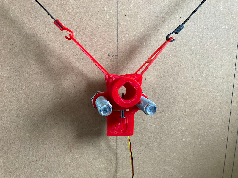
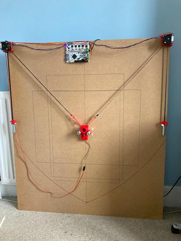
      A Polargraph is a 2D drawing machine, a vertically-mounted pen plotter with 2 motors in each top corner, and a pen suspended in a 'gondola' (or effector) in between. I've wanted to build one of these for a long time, but couldn't be bothered messing around with old-school Arduinos and RAMPS. Surely RepRapFirmware would support it? While there was the odd thread where it was suggested, there is no explicit Polargraph kinematics in RRF, so I shelved it for a long time, until @CNCModeller and @o_lampe in this thread https://forum.duet3d.com/topic/33992/control-for-maslow-style-cnc got me curious as to whether Hangprinter kinematics could actually support it. After looking at it for a bit, I thought it could...

      Looking around, the Makelangelo seemed the best developed Polargraph around. I printed out the parts for the most up-to-date gondola, selected the largest MDF sheet I had under the stairs, then printed two motor mounts from this version, ordered some big bolts for weights, and put it all together with parts from the parts box and a pre-production white PCB Duet 2 WiFi, running RRF 3.4.6 (the last version to have the Hangprinter kinematics on Duet 2 WiFi/Ethernet).

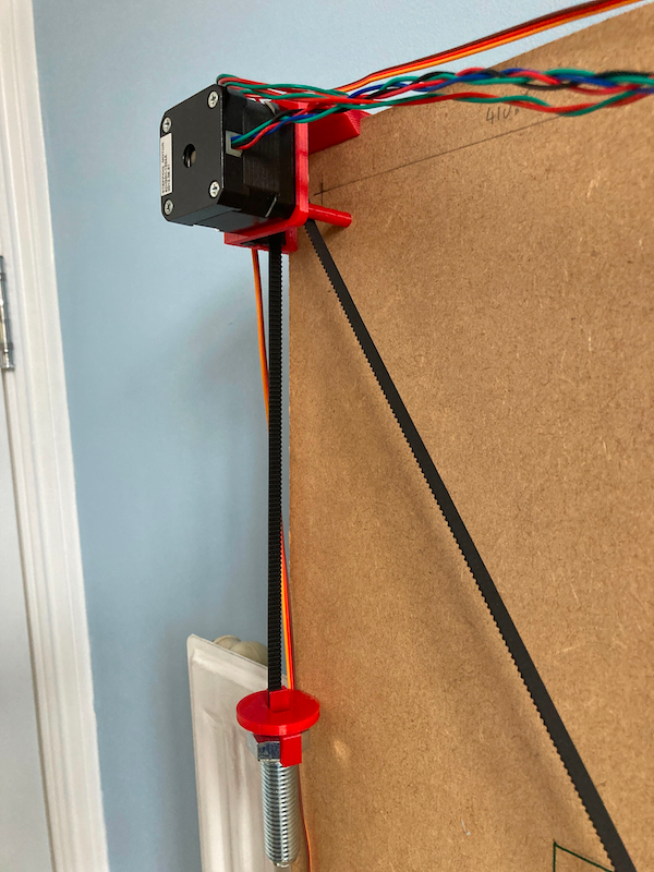
      After a bit of messing around with the config, and some initial tests, I realised that it was drawing curved horizontal lines towards the top of the print area. This was caused by the contact point on the motor pulley changing, the higher the pen was. To mitigate this, I added a standoff at the corner of each motor mount, that the belts touch against. This gives a more consistent 'anchor' point, as it now only wanders about 1mm in X and Y for the whole range of movement of the effector. Size is within 1mm of the A2 drawing area (420mm x 594mm, or 16.5" x 23.4" for users of freedom units), good enough for me. I added microswitch endstops at the same time, though I could probably have done homing with motor stalls. Also, tidying up the prints to remove seams dramatically improved smooth movement of the gondola. Currently, it looks like this:

      8210990f-5b15-4dc5-a852-b02cd4af0f89-image.png

      3fa49ec2-95f0-4d22-8402-c8f9276cdffc-image.png

      ac39b58a-5c08-44d6-8eeb-c44e1d60c3ab-image.png

      The landscape and portrait rectangles are A2 size. The lower arcs are the limit of where the pen can reach. I should have left the belts a bit longer, but these are the right size for the board, as the gondola homes at the bottom. Here's the current config.g:

      ; Configuration file for Duet WiFi (firmware version 3)
      ; executed by the firmware on start-up
      ;
      ; generated by RepRapFirmware Configuration Tool v2.1.6 on Tue Jan 14 2020 12:35:54 GMT+0000 (Greenwich Mean Time)
      
      ; General preferences
      G90                                                ; send absolute coordinates...
      M83                                                ; ...but relative extruder moves
      M550 P"Polarian"                                  ; set printer name
      
      ; Network
      M552 S1                                            ; enable network
      M586 P0 S1                                         ; enable HTTP
      M586 P1 S0                                         ; disable FTP
      M586 P2 S0                                         ; disable Telnet
      
      ; Drives
      M569 P0 S1 ; drive 0 (X motor output) 
      M569 P1 S1 ; drive 1 (Y motor output) 
      M569 P2 S1 ; drive 2 (Z motor output) 
      M569 P3 S1 ; drive 3 (E0 motor output) 
      M569 P4 S0 ; drive 4 (E1 motor output) 
      
      ; For Polargraph, anchor A is dummy motor below effector, anchor B is using Z driver, anchor C is using E1 driver
      ; In M584 X= anchor A (dummy), Y= anchor B (Z driver), Z= anchor C (E1 driver)
      
      M584 X0 Y2 Z4 U1 ; X=A, Y=B, Z=C and create U axis for the D dummy motor
      
      M350 X16 Y16 Z16 U16 I1                            ; configure microstepping with interpolation
      M92 X80.00 Y80.00 Z80.00 U80.00                  ; set steps per mm
      M566 X300.00 Y300.00 Z300.00 U300.00                ; set maximum instantaneous speed changes (mm/min)
      M203 X6000.00 Y6000.00 Z6000.00 U6000.00            ; set maximum speeds (mm/min)
      M201 X3000.00 Y3000.00 Z3000.00 U3000.00                ; set accelerations (mm/s^2)
      M906 X100 Y800 Z800 U100 I30                    ; set motor currents (mA) and motor idle factor in per cent
      M84 S30                                            ; Set idle timeout
      
      ; Kinematics
      M669 K6 A0:-1000:0 B396.5:422.5:0 C-396.5:422.5:0 D0:0:1000 P450 ; configure hangprinter kinematics
      ;M669 K6 A396.5:-422.5:0 B396.5:422.5:0 C-396.5:422.5:0 D-396.5:-422.5:0 P450
      M666 Q0.0001 R6.365:6.365:6.365:6.365 U1:1:1:1 L20:20:20:20 H20:20:20:20 J200:200:200:200
      
      ; Axis Limits
      M208 S0 Z200                                                ; set maximum height
      M208 S1 Z0                                                  ; set minimum height
      
      ; Endstops
      M574 Y1 S1 P"zstop"                                ; configure active-high endstop for high end on X via pin xstop
      M574 Z1 S1 P"e1stop"                                ; configure active-high endstop for low end on Y via pin ystop
      
      ; Tools
      M563 P0 S"Pen"                                     ; define tool 0
      G10 P0 X0 Y0 Z0                                    ; set tool 0 axis offsets
      G10 P0 R0 S0                                       ; set initial tool 0 active and standby temperatures to 0C
      
      ; Servo
      M950 S0 C"exp.heater3"
      
      ; Custom settings
      M912 P0 S1.5                                       ; MCU temperature offset
      
      ; Miscellaneous
      ;M501                                               ; load saved parameters from non-volatile memory
      M911 S11 R12 P"M913 X0 Y0" ; set voltage thresholds and actions to run on power loss
      T0                                                 ; select first tool
      

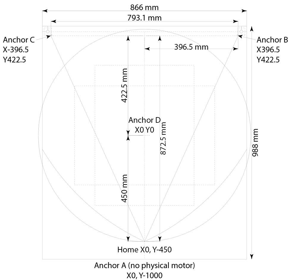
      A layout showing dimensions:

      505fc244-9654-4ae6-9e3e-d0eb35c52d70-image.png

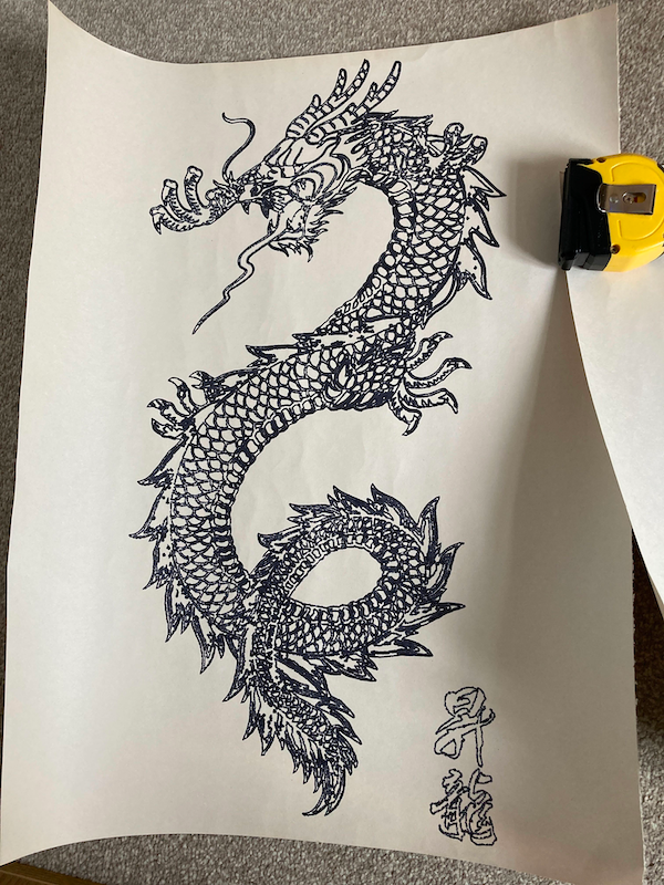
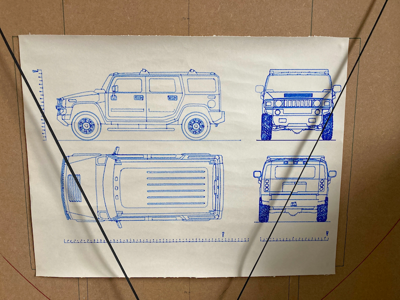
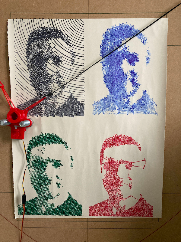
      And finally, some things I've actually got it to draw! Mostly I've used the Makelangelo software, which has a good amount of features, allows for import of svg files, and a fair number of filters for pixel images. @jay_s_uk has recently put me on to DrawingBotV3, which I intend to try out too.

      d7dd071c-3894-4263-8212-6e8e759d8559-image.png

      dcae1039-01b3-4efe-9aad-94ffc499b62c-image.png

      94d113a8-0d4e-41b3-a4c4-e4258e03a910-image.png

      I asked @tobben on the Hangprinter Discord about the kinematics, and he thinks the four anchors that Hangprinter uses can be placed anywhere (the documentation says the D anchor needs to be over X0 Y0). This opens up the possibility of some other cable-based machines:

      • Machines like the Maslow router, with a rigid rectangular frame and an anchor in each corner.
      • For a vertically mounted 4-cable polargraph (which would help stabilise the effector), you could have two motors each side at the top corners, and an idler at the bottom corner each side for the lower cables. Then weights for each corner can be hung, and move up and down.
      • For a roomcam/four point Hangprinter, you would have the 4 anchors on the ceiling, in the corners of the room. It wouldn't be as well constrained as a normal hangprinter, and I'd tend to have the motors in the corners, not on the effector. Or hanging off the lighting towers of a stadium, which is what they do with the Skycam, see https://en.wikipedia.org/wiki/Skycam

      Feel free to ask if you have any questions, I'm happy to elaborate!

      Ian

      posted in My Duet controlled machine
      droftartsundefined
      droftarts
    • RE: DUEX 5 V0.8 TO DUEX 5 V0.11

      @paolozampini1973 I'm not sure why you want to talk to dc42 about the design of the DueX. You want to argue with him that level shifters should be included? You want Duet3D to make a special board, just for you?

      When the Duet 2 and DueX boards were designed, in 2016, the industry was different, and the Duet 2 was focussed on 3D printers. There weren't many large printers that needed external driver support, and 5V signalling was seen as a very niche requirement. Enable, step and direction signals were made available over time to allow for external drivers (and many smaller drivers DO accept 3.3V signalling) but you are the first person that I've seen, in over 6 years, to actually complain that the DueX should have 5V signalling.

      The External Breakout Board (EBoB) was designed a year later so that Duet 2 could drive larger external drivers. I've explained how you can connect BOTH DueX and EBoB boards at the same time. The only limitation is that you can't use the same driver on the DueX as on the EBoB, so you are still limited to 5 drives total. So you can still use 3 drives on the DueX, eg E2, E3 and E4, then use E5 and E6 on the EBoB for external drivers.

      Realistically, Duet3D isn't doing any further design development to Duet 2. It's a stable product that people like as it is. The firmware is right at the limit now for it, though, and over time it will not be able to support new features. Duet3D are focussed on developing the Duet 3 boards, which probably would have been a better choice for your high end, custom machine; Duet 3 CAN bus boards for external drivers are available.

      If you want support to solve your problems, actually post some useful information:

      • Send M122 and post response
      • Post your current config.g
      • Explain the layout of your machine, clearly, and what stepper drives are connected where.
      • Post a picture of your wiring, and how you have configured the DueX
      • Actually list the 6 problems you are having, with as much information as possible, clearly and concisely.

      Because the 32 posts you've made to this thread contain virtually zero information that can be used to understand the issues you are having, and all you are doing is annoying the people who are trying to help you.

      Ian

      posted in Duet Hardware and wiring
      droftartsundefined
      droftarts
    • RE: 12864 Modification

      This thread is now locked. I'm sorry this has been necessary, but I want to wrap up the thread with the useful information for anyone following this thread.

      @A-Former-User said in 12864 Modification:

      question I have is, after the changes are made does the code need to be compiled?

      Yes. Generally, RepRapFirmware is monolithic and does not need to be recompiled; you just use the pre-compiled firmware and upload it to your Duet. However, if you need to add/change functionality, and actually edit the firmware source code as in this thread, you WILL need to set up the software to edit and compile the firmware as described in this link: https://github.com/dc42/RepRapFirmware/blob/dev/BuildInstructions.md

      @A-Former-User said in 12864 Modification:

      One more question, if you add support for the 12864 will the adapter board still be needed?

      Yes. Support for the 12864 comes in two parts; first support in firmware, and then some extra hardware, to level-shift the logic from 3.3V to 5V. The hardware and firmware support are already present in the Duet 2 Maestro version, but not in the Duet 2 WiFi/Ethernet.

      @DueDue said in 12864 Modification:

      It looks to me that the trend in the forums all over is to direct the person asking the question to some link.

      If any question can be answered with a link to documentation, that is the correct approach to minimise time spent on support. If the link doesn't completely answer the question, the original poster can always come back and ask more questions, and if necessary the documentation can be updated/improved. That saves everyone time.

      I think what went wrong here for the OP is that, by asking about editing the firmware, a level of knowledge was assumed by those answering. It might be simpler in Marlin (because it forces you to build the firmware every single time you want to change something, but at least the Arduino IDE is easy to set up), but for 99% of users, RepRapFirmware doesn't need to be compiled by the user; it is configured by editing a text file on the SD card, config.g. Setting up and using the build environment for RepRapFirmware is not trivial; I tried a couple of years ago, didn't get it working, haven't needed to try since. So the assumption is that, when someone asks about it, they know what they're doing. Asking questions such as "do I need to compile [after I've edited the firmware source files]" does rather make it sound like this may be a difficult task for the OP. It also seems like the OP skim-read (or didn't read) the links, so didn't quite appreciate the complexity of the task, eliciting the responses from more experienced users.

      If anyone has issues with this thread, I'm happy to moderate it, but generally we let things stand. Send me a PM, but note support is not provided by PM.

      Ian

      posted in General Discussion
      droftartsundefined
      droftarts
    • LED rainbow effects

      Recently I got a Mini12864 display, which has RGB Neopixels for the backlight and encoder wheel. I played around trying to set colours, but then thought it was a 'good' idea to get a rainbow effect working, for fun. I couldn't find much other RRF documentation on this, and eventually realised that using meta Gcode would make it easier, and helped as a simple project to start using meta Gcode.

      To start off with, this is using a Duet 3 Mini 5+. I started off on RRF 3.4, then moved to the RRF 3.5 beta. Some of the code below will work with older versions of RRF. The relevant bits of config.g to set up the screen and LEDs (yours may be different if using a different board/LED combo/RRF version):

      M918 P2 E-4 C70 R4             ; enable MKS Mini12864
      M150 X2 R60 U255 B0 P255 S3 F0 ; set LEDs for MKS Mini12864
      

      First, I found RGB colours for the seven colours of the rainbow. I put these in a spreadsheet, and generated the colours in between, to create a straight Gcode file that changed the colour. Note that on my screen, colours are ordered GRB rather than RGB, so U=red, R=green, B=blue in M150:

      M150 U148 R0 B211 S3 F0
      G4 P100
      M150 U141 R0 B203 S3 F0
      G4 P100
      M150 U133 R0 B195 S3 F0
      G4 P100
      M150 U126 R0 B187 S3 F0
      G4 P100
      M150 U119 R0 B179 S3 F0
      G4 P100
      M150 U112 R0 B171 S3 F0
      G4 P100
      M150 U104 R0 B162 S3 F0
      G4 P100
      M150 U97 R0 B154 S3 F0
      G4 P100
      M150 U90 R0 B146 S3 F0
      G4 P100
      M150 U82 R0 B138 S3 F0
      G4 P100
      M150 U75 R0 B130 S3 F0
      G4 P100
      M150 U68 R0 B143 S3 F0
      G4 P100
      M150 U60 R0 B155 S3 F0
      G4 P100
      M150 U53 R0 B168 S3 F0
      G4 P100
      M150 U45 R0 B180 S3 F0
      G4 P100
      M150 U38 R0 B193 S3 F0
      G4 P100
      M150 U30 R0 B205 S3 F0
      G4 P100
      M150 U23 R0 B218 S3 F0
      G4 P100
      M150 U15 R0 B230 S3 F0
      G4 P100
      M150 U8 R0 B243 S3 F0
      G4 P100
      M150 U0 R0 B255 S3 F0
      G4 P100
      M150 U0 R26 B230 S3 F0
      G4 P100
      M150 U0 R51 B204 S3 F0
      G4 P100
      M150 U0 R77 B179 S3 F0
      G4 P100
      M150 U0 R102 B153 S3 F0
      G4 P100
      M150 U0 R128 B128 S3 F0
      G4 P100
      M150 U0 R153 B102 S3 F0
      G4 P100
      M150 U0 R179 B77 S3 F0
      G4 P100
      M150 U0 R204 B51 S3 F0
      G4 P100
      M150 U0 R230 B26 S3 F0
      G4 P100
      M150 U0 R255 B0 S3 F0
      G4 P100
      M150 U26 R255 B0 S3 F0
      G4 P100
      M150 U51 R255 B0 S3 F0
      G4 P100
      M150 U77 R255 B0 S3 F0
      G4 P100
      M150 U102 R255 B0 S3 F0
      G4 P100
      M150 U128 R255 B0 S3 F0
      G4 P100
      M150 U153 R255 B0 S3 F0
      G4 P100
      M150 U179 R255 B0 S3 F0
      G4 P100
      M150 U204 R255 B0 S3 F0
      G4 P100
      M150 U230 R255 B0 S3 F0
      G4 P100
      M150 U255 R255 B0 S3 F0
      G4 P100
      M150 U255 R242 B0 S3 F0
      G4 P100
      M150 U255 R229 B0 S3 F0
      G4 P100
      M150 U255 R217 B0 S3 F0
      G4 P100
      M150 U255 R204 B0 S3 F0
      G4 P100
      M150 U255 R191 B0 S3 F0
      G4 P100
      M150 U255 R178 B0 S3 F0
      G4 P100
      M150 U255 R165 B0 S3 F0
      G4 P100
      M150 U255 R153 B0 S3 F0
      G4 P100
      M150 U255 R140 B0 S3 F0
      G4 P100
      M150 U255 R127 B0 S3 F0
      G4 P100
      M150 U255 R114 B0 S3 F0
      G4 P100
      M150 U255 R102 B0 S3 F0
      G4 P100
      M150 U255 R89 B0 S3 F0
      G4 P100
      M150 U255 R76 B0 S3 F0
      G4 P100
      M150 U255 R64 B0 S3 F0
      G4 P100
      M150 U255 R51 B0 S3 F0
      G4 P100
      M150 U255 R38 B0 S3 F0
      G4 P100
      M150 U255 R25 B0 S3 F0
      G4 P100
      M150 U255 R13 B0 S3 F0
      G4 P100
      M150 U255 R0 B0 S3 F0
      G4 P100
      

      This works, changing all three LEDs through the colours, and should work with RRF back to v3.3 (and possibly earlier depending on your LEDs) . But changing the colours is time-consuming, and it doesn't oscillate through the LEDs. Perhaps I could do better ...
      This is the eventual macro using meta Gcode, and should work with RRF 3.3 and later:

      var Red1 = 148
      var Red2 = 75
      var Red3 = 0
      var Red4 = 0
      var Red5 = 255
      var Red6 = 255
      var Red7 = 255
      
      var Green1 = 0
      var Green2 = 0
      var Green3 = 0
      var Green4 = 255
      var Green5 = 255
      var Green6 = 127
      var Green7 = 0
      
      var Blue1 = 211
      var Blue2 = 130
      var Blue3 = 255
      var Blue4 = 0
      var Blue5 = 0
      var Blue6 = 0
      var Blue7 = 0
      
      var Interpolation = 5
      
      while iterations<7
      
      	var RedA = (iterations = 0) ? var.Red1 : (iterations = 1) ? var.Red2 : (iterations = 2) ? var.Red3 : (iterations = 3) ? var.Red4 : (iterations = 4) ? var.Red5 : (iterations = 5) ? var.Red6 : (iterations = 6) ? var.Red7 : var.Red1
      	var GrnA = (iterations = 0) ? var.Green1 : (iterations = 1) ? var.Green2 : (iterations = 2) ? var.Green3 : (iterations = 3) ? var.Green4 : (iterations = 4) ? var.Green5 : (iterations = 5) ? var.Green6 : (iterations = 6) ? var.Green7 : var.Green1
      	var BluA = (iterations = 0) ? var.Blue1 : (iterations = 1) ? var.Blue2 : (iterations = 2) ? var.Blue3 : (iterations = 3) ? var.Blue4 : (iterations = 4) ? var.Blue5 : (iterations = 5) ? var.Blue6 : (iterations = 6) ? var.Blue7 : var.Blue1
      	
      	var RedB = (iterations = 0) ? var.Red2 : (iterations = 1) ? var.Red3 : (iterations = 2) ? var.Red4 : (iterations = 3) ? var.Red5 : (iterations = 4) ? var.Red6 : (iterations = 5) ? var.Red7 : (iterations = 6) ? var.Red1 : var.Red1
      	var GrnB = (iterations = 0) ? var.Green2 : (iterations = 1) ? var.Green3 : (iterations = 2) ? var.Green4 : (iterations = 3) ? var.Green5 : (iterations = 4) ? var.Green6 : (iterations = 5) ? var.Green7 : (iterations = 6) ? var.Green1 : var.Green1
      	var BluB = (iterations = 0) ? var.Blue2 : (iterations = 1) ? var.Blue3 : (iterations = 2) ? var.Blue4 : (iterations = 3) ? var.Blue5 : (iterations = 4) ? var.Blue6 : (iterations = 5) ? var.Blue7 : (iterations = 6) ? var.Blue1 : var.Blue1
      	
      	var RedC = (iterations = 0) ? var.Red3 : (iterations = 1) ? var.Red4 : (iterations = 2) ? var.Red5 : (iterations = 3) ? var.Red6 : (iterations = 4) ? var.Red7 : (iterations = 5) ? var.Red1 : (iterations = 6) ? var.Red2 : var.Red1
      	var GrnC = (iterations = 0) ? var.Green3 : (iterations = 1) ? var.Green4 : (iterations = 2) ? var.Green5 : (iterations = 3) ? var.Green6 : (iterations = 4) ? var.Green7 : (iterations = 5) ? var.Green1 : (iterations = 6) ? var.Green2 : var.Green1
      	var BluC = (iterations = 0) ? var.Blue3 : (iterations = 1) ? var.Blue4 : (iterations = 2) ? var.Blue5 : (iterations = 3) ? var.Blue6 : (iterations = 4) ? var.Blue7 : (iterations = 5) ? var.Blue1 : (iterations = 6) ? var.Blue2 : var.Blue1
      	
      	var RedD = (iterations = 0) ? var.Red4 : (iterations = 1) ? var.Red5 : (iterations = 2) ? var.Red6 : (iterations = 3) ? var.Red7 : (iterations = 4) ? var.Red1 : (iterations = 5) ? var.Red2 : (iterations = 6) ? var.Red3 : var.Red1
      	var GrnD = (iterations = 0) ? var.Green4 : (iterations = 1) ? var.Green5 : (iterations = 2) ? var.Green6 : (iterations = 3) ? var.Green7 : (iterations = 4) ? var.Green1 : (iterations = 5) ? var.Green2 : (iterations = 6) ? var.Green3 : var.Green1
      	var BluD = (iterations = 0) ? var.Blue4 : (iterations = 1) ? var.Blue5 : (iterations = 2) ? var.Blue6 : (iterations = 3) ? var.Blue7 : (iterations = 4) ? var.Blue1 : (iterations = 5) ? var.Blue2 : (iterations = 6) ? var.Blue3 : var.Blue1
      	
      	while var.Interpolation != iterations
      		
      		var r1 = floor(var.RedA + ((var.RedB - var.RedA) / var.Interpolation ) * iterations)
      		var g1 = floor(var.GrnA + ((var.GrnB - var.GrnA) / var.Interpolation ) * iterations)
      		var b1 = floor(var.BluA + ((var.BluB - var.BluA) / var.Interpolation ) * iterations)
      		
      		var r2 = floor(var.RedB + ((var.RedC - var.RedB) / var.Interpolation ) * iterations)
      		var g2 = floor(var.GrnB + ((var.GrnC - var.GrnB) / var.Interpolation ) * iterations)
      		var b2 = floor(var.BluB + ((var.BluC - var.BluB) / var.Interpolation ) * iterations)
      		
      		var r3 = floor(var.RedC + ((var.RedD - var.RedC) / var.Interpolation ) * iterations)
      		var g3 = floor(var.GrnC + ((var.GrnD - var.GrnC) / var.Interpolation ) * iterations)
      		var b3 = floor(var.BluC + ((var.BluD - var.BluC) / var.Interpolation ) * iterations)
      		
      		M150 U{var.r1} R{var.g1} B{var.b1} P255 S1 F1
      		M150 U{var.r2} R{var.g2} B{var.b2} P255 S1 F1
      		M150 U{var.r3} R{var.g3} B{var.b3} P255 S1 F0
      		G4 P50
      

      But with arrays now available in RRF 3.5, it can be improved ...

      var Red = {148,75,0,0,255,255,255}
      var Green = {0,0,0,255,255,127,0}
      var Blue = {211,130,255,0,0,0,0}
      
      var Colours = 7
      var Interpolation = 10
      
      while iterations < 21
      	
      	; First LED colour, this loops the colour array using mod
      	var LED1r = var.Red[mod(iterations,var.Colours)]
      	var LED1g = var.Green[mod(iterations,var.Colours)]
      	var LED1b = var.Blue[mod(iterations,var.Colours)]
      	
      	; Second LED colour
      	var LED2r = var.Red[mod(iterations+1,var.Colours)]
      	var LED2g = var.Green[mod(iterations+1,var.Colours)]
      	var LED2b = var.Blue[mod(iterations+1,var.Colours)]
      	
      	; Third LED colour
      	var LED3r = var.Red[mod(iterations+2,var.Colours)]
      	var LED3g = var.Green[mod(iterations+2,var.Colours)]
      	var LED3b = var.Blue[mod(iterations+2,var.Colours)]
      	
      	; For more LEDS, add LED with RGB offset from previous LED here.
      	
      	; Last colour, needed so the last LED has a colour to change to 
      	var LED4r = var.Red[mod(iterations+3,var.Colours)]
      	var LED4g = var.Green[mod(iterations+3,var.Colours)]
      	var LED4b = var.Blue[mod(iterations+3,var.Colours)]
      	
      	while var.Interpolation != iterations
      		
      		; set the first LED colour based on the iteration
      		var r1 = floor(var.LED1r + ((var.LED2r - var.LED1r) / var.Interpolation) * iterations)
      		var g1 = floor(var.LED1g + ((var.LED2g - var.LED1g) / var.Interpolation) * iterations)
      		var b1 = floor(var.LED1b + ((var.LED2b - var.LED1b) / var.Interpolation) * iterations)
      		
      		var r2 = floor(var.LED2r + ((var.LED3r - var.LED2r) / var.Interpolation) * iterations)
      		var g2 = floor(var.LED2g + ((var.LED3g - var.LED2g) / var.Interpolation) * iterations)
      		var b2 = floor(var.LED2b + ((var.LED3b - var.LED2b) / var.Interpolation) * iterations)
      		
      		var r3 = floor(var.LED3r + ((var.LED4r - var.LED3r) / var.Interpolation) * iterations)
      		var g3 = floor(var.LED3g + ((var.LED4g - var.LED3g) / var.Interpolation) * iterations)
      		var b3 = floor(var.LED3b + ((var.LED4b - var.LED3b) / var.Interpolation) * iterations)
      		
      		M150 U{var.r1} R{var.g1} B{var.b1} P255 S1 F1
      		M150 U{var.r2} R{var.g2} B{var.b2} P255 S1 F1
      		M150 U{var.r3} R{var.g3} B{var.b3} P255 S1 F0
      		G4 P50
      

      This is a little expansive, but relatively easy to read to understand what is going on. I'm sure it could be reduced in size and complexity, as I'm not much of a programmer, so feel free to suggest improvements. But I hope someone might find this useful, if only as a meta Gcode example!

      Ian
      posted in Gcode meta commands
      droftartsundefined
      droftarts
    • RE: Duet Polargraph

      Polargraph Update...

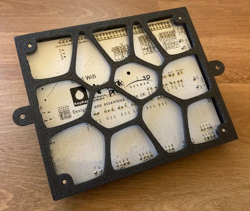
      I took the Polargraph to SMRRF 2024 in Manchester last weekend. As it was mounted on a large MDF sheet, and I was travelling by train, this required a little bit of re-engineering. I re-mounted it on a strip of MDF, the same width as the original piece (so I didn't have to change the config), and updated the motor mounts so the belts hang closer to the wall, as there was now a step down from the motors to the drawing surface. I also did a nice Voronoi case for Duet boards (produced the Voronoi in Inkscape, which I spent far to long playing around with, see https://youtu.be/0fzJdGRzjf8 then extruded that in Fusion 360), but of course that was invisible as it was behind the Duet!

      When I got to Manchester, @T3P3Tony insisted that I update it from the old, white PCB prototype Duet 2 WiFi, to a Duet 3 Mini 5+. This induced some headaches, as I eventually realised the comments in the config.g relating to anchor positions and motors was not correct in the original version. I have updated the config.g first post in this thread so it is now correct. I also removed the endstops, intending to make homing sensorless, but didn't get around to that, and just ended up homing manually. It was mounted on a white board, so easy to wipe off the board and draw something else. I'm sure that says something about the impermanence yet repeatability of art...

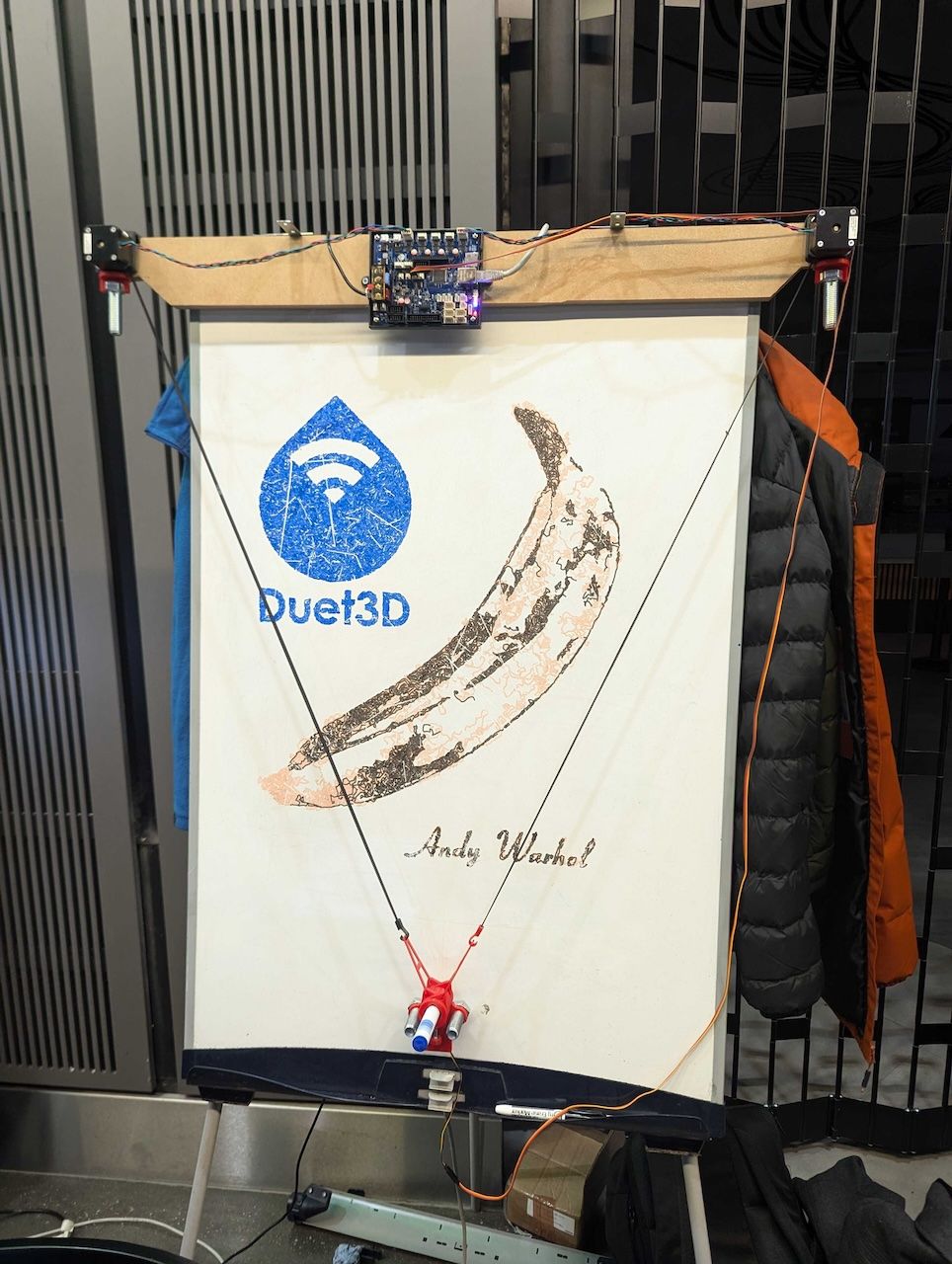
      Apart from that, it ran smoothly for the weekend. It mostly drew things I'd created before, but I eventually got around to doing a couple of new things. There was a bit of an Andy Warhol/art theme (there were some impressive Hueforge prints), so I used DrawingBot to produce some of my own:

      pxl_20241208_155202432.jpg

      Here's the Voronoi case. Let me know if you want the stl.

      IMG_8320.jpg

      Ian

      posted in My Duet controlled machine
      droftartsundefined
      droftarts
    • Gcode documentation change

      Over time, the single Gcode reference page has become huge, and was causing slow loading times from both the server and with some clients. It was also becoming increasingly difficult to edit (you only get a small window to edit in) and to navigate the page (it's easy to get lost as you scroll).

      Due to this, we have reorganised the Gcode page to have links to individual pages for each Gcode. It still has a heading for each Gcode, and a short description. The heading means that all old links to the Gcode dictionary should still work, though take you to the short entry with a link to the individual page, eg https://duet3d.dozuki.com/Wiki/Gcode#Section_M584_Set_drive_mapping. You can, of course, link directly to a page, for example https://duet3d.dozuki.com/Wiki/M584. This will also allow us to put more detail in for each Gcode.

      Another advantage is that it should be easier to have a Gcode highlighter/lookup in DWC now, something similar to what @theKM did recently in this thread https://forum.duet3d.com/topic/24970/handy-way-to-browse-gcode-docco-directly-from-the-gcode

      There's also an updated 'Gcode by function' page, here: https://duet3d.dozuki.com/Wiki/GCodes_index_by_function

      If there's any issues with this change, or suggestions for improvement, please post here.

      Ian

      posted in General Discussion
      droftartsundefined
      droftarts
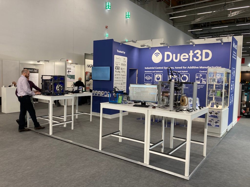
    • RE: Formnext 2023

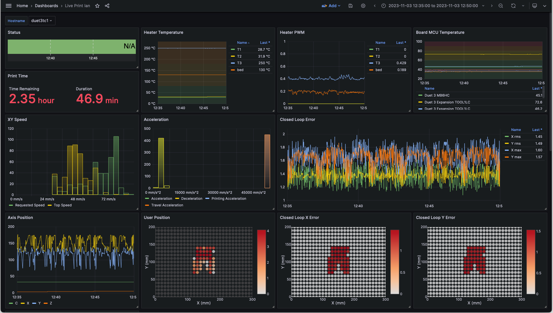
      Already the end of day 3! As usual, very busy here with lots of visitors to the stand and interest in what we offer. We're focussing on the new scanning Z probe (see the blog post here), our closed loop boards and the new closed loop stepper motors M23CL, and 'Data Collection' - expect a blog post on this at some point, but basically we use the REST API to extract data from the Duet Object Model, which is then stored in a database, and can then be queried by whatever tool you want. We're currently using Grafana to visualise the data, and it is really interesting to see the data plotted over time. What do you think you could use this for?!

      Grafana screenshot.png

      Here's some shots from the show (before it opened, so nice and quiet!):

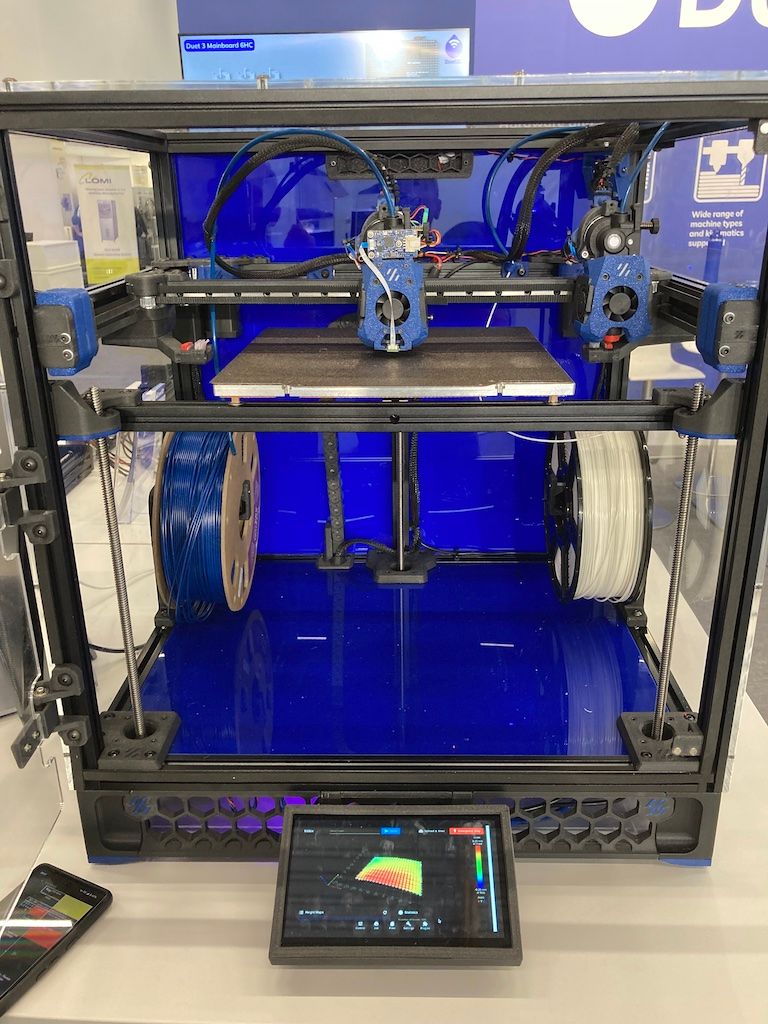
      Voron Tridex (Trident with IDEX) showcasing our new inductive probe, which scans 399 points on the bed in 15 seconds. The tools are Orbiter v2 with Mellow Fly 36RRF toolboards (I think, thanks @jay_s_uk!)

      IMG_7604.jpeg

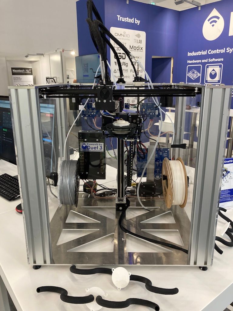
      E3D Toolchanger with open5x axis, E3D Revo Roto tool with the new E3D/Duet 3 Roto Tool Board and longer 'belt' Revo nozzle (for belt printers, but works well for 5-axis printing too!)

      IMG_7606.jpeg

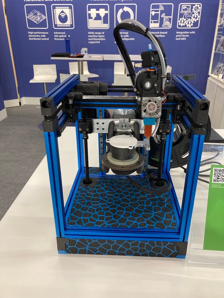
      'Cute' Voron 0 with open5x axis. Uses a Duet 3 Mini 5+ with Mini 2+ expansion for the six motors it needs.

      IMG_7605.jpeg

      And finally a picture of the stand, before the show opened. @T3P3Tony just visible, @dc42 just behind him.

      IMG_7603.jpeg

      Ian

      posted in General Discussion
      droftartsundefined
      droftarts
    • RE: dozuki.com

      @MartinMV I think you have chosen the wrong hobby. You have the strangest attitude, being rude to people who have been nothing but professional and helpful with you. You fail to provide information for us to help you. You moan about documentation and customer experience, but you have been supplied with fast and accurate responses, and plentiful documentation links. If you have questions, ask them. Being negative doesn't help you.

      I assume you are installing a Duet board on a printer that has a broken controller board; again, some explanation of what you're trying to do would be helpful. Maybe you should have replaced it with the same board, from the manufacturer. Otherwise, any controller board/firmware is going to need configuration. Duet boards probably have the most in-depth documentation of ANY controller board, being open source, and a strong community around using them. Try doing this with a Chinese board.

      Until I get any substantive, specific information from you, there is little point in replying to you.

      Ian

      EDIT: Also, read the forum rules: https://forum.duet3d.com/topic/20759/forum-rules
      And guide for requesting help: https://forum.duet3d.com/topic/5909/guide-for-posting-requests-for-help

      posted in Firmware installation
      droftartsundefined
      droftarts
    • RE: Robotic kinematics

      @o_lampe said in Robotic kinematics:

      @jay_s_uk Hmmm,
      like Winter soldier?

      My Bucky cosplay is at 1%.

      bucky.jpg

      Ian

      posted in MultiAxis Printing
      droftartsundefined
      droftarts

    Latest posts made by droftarts

    • RE: Error: Cannot read file, error code 1. Cancelled printing

      @R006 sounds like a full or failing SD card. Please run the tests described here: https://docs.duet3d.com/en/User_manual/RepRapFirmware/SD_card#troubleshooting-sd-card-issues

      Ian

      posted in Using Duet Controllers
      droftartsundefined
      droftarts
    • RE: Configurazione bl touch antclabs

      @perfetto

      Good morning, I need some clarification, the procedure you indicated regarding the sys folder to be renamed with old concerns the sys that I find in the www folder?

      No. It was for the /sys folder, so you could keep it as a back up, and create a new empty /sys folder. I didn’t know you had a sys folder in www, and also the firmware will ignore it. The www folder is not the correct place for the sys folder.

      Please try the config files I supplied, and follow the Commissioning guide. If you change any configuration files, you need to post them so I can see what has changed.

      Ian

      posted in General Discussion
      droftartsundefined
      droftarts
    • RE: Creatbot F430, проблема с осью X

      @wedmak19860104

      I don't understand what's wrong, everything is fine with the program. When starting printing with the second extruder, it cuts into the left guide, what could be the reason? Moreover, if you send it home, the limit switches work normally.

      More information required. Post config.g, any other relevant files, and the response to M122. Provide a better description of the printer, and what steps you are taking that cause the problem.

      Ian

      posted in General Discussion
      droftartsundefined
      droftarts
    • RE: Prusaslicer with Duet3D mini5 based printer profile

      @handyandy I think you asked this previously https://forum.duet3d.com/topic/37922/duet-3-mini-5-vs-prusa-mk4

      Perhaps start with the same settings as the Mk4, and tune extrusion (temperature, extrusion steps per mm) and see if you get similar results.

      Ian

      posted in General Discussion
      droftartsundefined
      droftarts
    • RE: Configurazione bl touch antclabs

      @perfetto said in Configurazione bl touch antclabs:

      Good evening.

      The first detail is this:
      in the sd card I find these folders;
      firmware
      gcodes
      macros
      sys
      www
      if I open the www folder inside I also find a sys folder that contains this
      confg1.txt

      if I open the sys folder that is between gcode and www I find thisconfig 2.txt

      With the first test I did I canceled the sys-old located in the www folder, then I adapted the config of the sys folder that I actually find in the system via web control,
      the printer went crazy, when I launched home bltouch it doesn't work the x and the y go towards + and not towards the limit switches 0, the z went up like a rocket and then went down again, I stopped with emergency to avoid collision.
      thanks

      The config in the www folder will be ignored, only the one in sys is used. If you have changed the config.g I provided, you need to post it.

      Ian

      posted in General Discussion
      droftartsundefined
      droftarts
    • RE: external motors compatibility

      @kumar22222 How many motors are you planning on connecting? Just one? Are you going to have a mix of closed loop motors on drivers, and open loop motors?

      For your motor drivers, see the driver manual, page 3: https://www.omc-stepperonline.com/download/CL57T_V4.0.pdf

      It has this table:

      PIN I/O Details
      PUL+ (CW+) I Pulse and Direction Connection: (1) Optically isolated, high level 3.5-5V or 24V, low voltage 0-0.5V (2) Maximum 500 KHz input frequency (3) The width of PUL signal is at least 1.0μs, duty cycle is recommended 50% (4) Single pulse (step & direction) or double pulse (CW/CCW) is set by DIP Switch SW7 (5) DIR signal requires advance PUL signal minimum 2 μs in single pulse mode (6) The factory setting of control signal voltage is 24V, must need to set S3 (figure 2) if it is 5V
      PUL- (CW-) I
      DIR+ (CCW+) I
      DIR- (CCW-) I
      ENA+ I Enable Signals: Optional. (1) Effective high level is 3.5-24V; Effective low level is 0-0.5V connection (2) ENA signal requires advance DIR signal minimum 200ms in single pulse mode, (default no connection)
      ENA- I

      So it looks like in needs over 3.5V signalling. It might work with 3.3V signalling, but it might also not be reliable. You can:

      1. Use a Duet 3 Mini 5+, directly connect the motor to the Mini 5+ and run it in open loop mode, but because of the lower current stepper drivers on the Mini 5+, you won't get the full performance the motor could provide.
      2. Use a Duet 3 Mini 5+ for up to two external drivers directly, but may not work with 3.3V signalling.
      3. Use a Duet 3 Mini 5+, and use 3.3V to 5V level shifting ICs such as 74HCT04 to boost the signal level to 5V and drive them.
      4. The Duet 3 6HC cannot drive external drivers directly, so you will need to use an external CAN-connected expansion board. If you don't need to run the motor in closed loop mode, you can directly connect the motor to the 6HC without using the external driver, it has higher current drivers than the Mini 5+.
      5. Use a Duet 3 mainboard with a Duet 3 Expansion 1XD to provide 5V signalling to control the external driver. See https://docs.duet3d.com/Duet3D_hardware/Duet_3_family/Duet_3_Expansion_1XD
      6. Use a Duet 3 mainboard with the motor directly connected to a Duet 3 Expansion 1HCL, which provides closed loop control of the motor that is integrated into the Duet 3 firmware ecosystem (better feedback and more control of the motor). The external driver is redundant in this setup. See https://docs.duet3d.com/Duet3D_hardware/Duet_3_family/Duet_3_Expansion_1HCL
      7. If you don't need to connect any 'normal' open loop stepper motors, you could use the Duet 3 6XD mainboard, that provides 6x external driver connections. See https://docs.duet3d.com/Duet3D_hardware/Duet_3_family/Duet_3_Mainboard_6XD_Hardware_Overview

      Ian

      posted in Duet Hardware and wiring
      droftartsundefined
      droftarts
    • RE: external motors compatibility

      @kumar22222 See https://docs.duet3d.com/User_manual/Connecting_hardware/Motors_connecting_external

      The Mini 5+ can support two external drivers, connected directly to the mainboard, so long as the external driver can accept 3.3V single-ended signalling. Otherwise, you can connect them to a Duet 3 1XD external driver board, connected to the Mini 5+ via CAN.

      Ian

      posted in Duet Hardware and wiring
      droftartsundefined
      droftarts
    • RE: Closed loop firmware for CNC

      @o_lampe said in Closed loop firmware for CNC:

      AFAIK, the current closed loop strategy in RRF is to add the missed steps to the axis involved.

      I don't think that is correct. RRF sends a profile of the move via CAN, not step pulses. In closed loop mode, the 1HCL moves to the position at the speed dictated by the move profile. It doesn't really use steps; it uses the feedback from the encoder to position the motor. If the motor isn't keeping position, it increases current (up to a defined limit) until the motor has enough torque to achieve position. If it still can't keep position, it raises a driver error.

      Ian

      posted in CNC
      droftartsundefined
      droftarts
    • RE: Configurazione bl touch antclabs

      @perfetto said in Configurazione bl touch antclabs:

      Good morning, I tried to set up the machine with the configurator 3.5 I uploaded the zipped file via web interface, the bl touch works the temperatures are managed, the machine does not run the home.
      In the file systems there are many strange things I send you the files

      Please see my post above. If there are problems, please explain each one clearly.

      Ian

      posted in General Discussion
      droftartsundefined
      droftarts
    • RE: Configurazione bl touch antclabs

      @perfetto said in Configurazione bl touch antclabs:

      just one thing the home must be x0 y-5

      Here is an updated configuration: perfetto config.zip.txt
      Download this, delete the ".txt" from the end, and unzip the .zip file. (The forum does not allow .zip files to be uploaded.)

      I recommend you rename the existing 'sys' folder on the SD card to 'sys_old', and copy the contents of the .zip file above to a new 'sys' folder on the SD card.

      The config.g is quite similar to your "versione 3.5.1.txt", but I have changed a lot of the values so they are the same as your "config.g funzionante 2020.txt". See the differences here: https://www.diffchecker.com/gZTQOoak/

      After you restart the Duet, please follow the 'Commissioning' guide, to check everything is working, here: https://docs.duet3d.com/en/How_to_guides/Commissioning
      If anything is not working, let me know. Provide as much detail as possible.

      Ian

      posted in General Discussion
      droftartsundefined
      droftarts