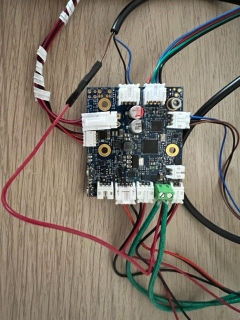
ToolBoard 1LC - wiring a NPN NC inductive sensor
-
hi all, I'm trying to figure out the "cleanest" way to wire a NPN NC inductive sensor directly to the 1LC toolboard. likely my question is silly, but probably someone can quickly answer: I would use the "IO_0" connector, connecting "GND" and "io0.in" to the sensor "GND and "SIGNAL", my doubt is the right way to get the "V+". is it fine to derive it directly from the "POWER IN" connector?
thanks
ciao
Andrea -
@Jiarko yes you can get power for the sensor from the VIN connector, or alternatively from any of the three OUT connectors.
-
@dc42 I've wired the probe and set the following
M558 P8 C"!121.io0.in" H5 F120 T6000into the "config.g" file . I'm trying to figure out if everything works fine but I can't find a way to check if the sensor is correctly set.
I see the power of the sensor is ok; when I put some metal obj close to the sensor led switches off, but I cannot detect via DWC if the system is working fine (i.e. the zProbe input is triggering the signal).
If I go into DWC "machine specific - endstops" (the plugin I've loaded) the "Z axis" never change its status.
If I go in the "object Model" and search for "sensor - endstops" I see
highEnd = false
triggered = false
type = "zProbeAsEndStop"
If I send M119 command I see " Endstops - X: not stopped, Y: not stopped, Z: at min stop, Z probe: at min stop"
is there a way to check everything is fine (before assemblying the whole printer mechanics)?
thanks, ciao
Andrea -
@Jiarko for a NC NPN sensor you should omit the ! in the pin name.
Please post photos showing how you have wired the sensor to the tool board.
-
@dc42 here a photo: I've taken the power from the hotend terminal, than I've connected GND and "io0.in" of the "IO_0" connector.
I've omitted the "!" as you suggested, but now in the DWC I see the zProbe reading 1000 with the red bckg. is this correct? I thought it should be the opposite. In fact now in the "endstop" plugin I see Z as triggered, no matter if it is really triggered or not...

-
@Jiarko it looks to me that you have the ground and output wires swapped. The usual colour code for NPN sensors is that blue is ground and black is output.
-
@dc42 you are (obviously) right... I have wrongly connected the sensor wires.
now it's fixed!! thanks!!!
just one more question: if I want to have two "z" sensor, one for bed leveling and one for "safety", is it possible? do you have any recommendation (maybe it's not useful at all)?
-
@Jiarko you could have a second Z sensor that triggers a little below the main one and causes an emergency stop. You would need to make sure that it triggers later than the main one at all reachable XY coordinates.
-
@dc42 thanks again!!! to me this topic is clearly solved!!! thanks for your time!!
-
 undefined dc42 marked this topic as a question
-
 undefined dc42 has marked this topic as solved