YAT problem for COM3 serial port
-
@Phaedrux hello,
I try to use powered USB hub, but the communication refused.
But my usb ports of laptop does not work since I plug the powered usb hub. Maybe my duet is wrong?
Another computer can not be join the duet via usb, and the problem is same as upper mentioned... -
Keep trying different USB ports/cables. What kind of powered hub did you find?
Is the other computer also a laptop?
-
sorry for late answer, but i try to connect another method via usb port... powered usb hub is dangerous if not dedicated hub can be used to connection. Cheap powered us hub is damage the laptop or duet board. Dedicated powered usb hub is very expensive.
i try to connect y-usb cable ( 2 male and 1 female cable), see the picture
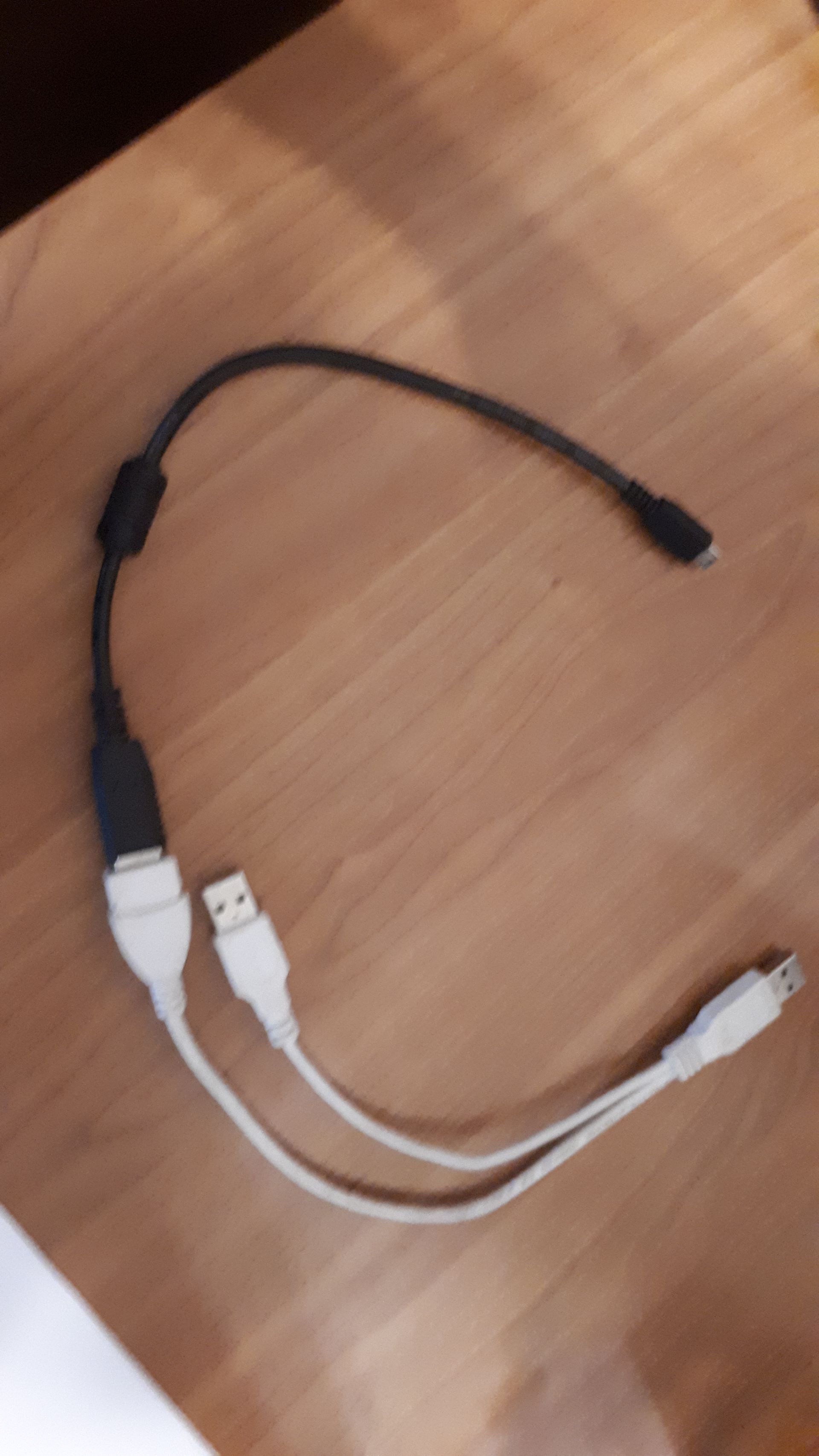
The connection is estalished by this Y usb cable. So i can set the wifi connection in board, and the web control can be communicate the board (without any cables). But i mount to the printer and the board is wired according to documentation, the board is not responding...
So my board is damaged, so the electrician expert have to change any mosfet beside fan ports...
I wait for your work...
The base problem is solved: original (blue) usb cable or Y-usb cable have been connected to the board, so the web commuication/ yat communication is established .thanks, JR
-
@jonasr75 said in YAT problem for COM3 serial port:
the board is not responding...
https://docs.duet3d.com/en/User_manual/Troubleshooting/Duet_wont_respond
Take a look through that and let me know what you find.
-
@Phaedrux okay, i will check it, and i will send to you any info to this procedure
-
@Phaedrux hello, here is the test for my duet2wifi board.
there is no panel due
no SBD
Do not apply VIN power to the Duet at this point. -->OK
"Duet 2: There should be a red LED illuminated between the USB connector and the Reset button. The red 5V LED at the edge of the board should also be lit, so should the green 3.3V LED."
the led between the usb and the reset button lights up blue (not red) 3.3V led lights up green, that's OK. The 5V led does not light up red, only weak green.
The DIAG led does not light up, even when I connect the USB cable. According to the document, the DIAG led when the USB is plugged in approx. It lights up for 0.5 seconds and then goes off normally. Nothing happens here.
I removed all connections but nothing changed. I removed the SD card and pressed the reset button, but still no change. See the picture (sorry if the quality is a bit poor, but the 3 LEDs are visible)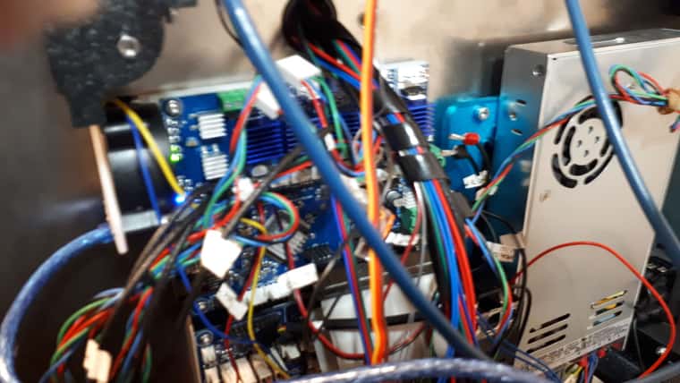
The USB power supply is sufficient, because another borrowed board recognizes the device after installing the driver, and then the YAT can connect to it.
see the another pic:
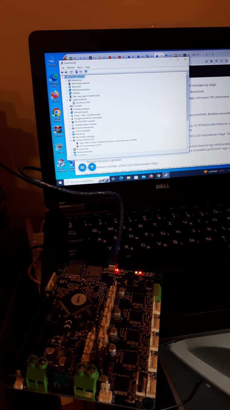
I look forward to your help,
JR -
I removed all connections but nothing changed. I removed the SD card and pressed the reset button
Looks like you spared some Forint, your board seems not to be genuine. Heat sinks and LED colours indicate that. This makes it difficult to diagnose hardware problems. However, you can locate the LEDs and their meanings with the help of this schematic: LED indications.
From your reports, I have the impression that the 5V rail draws too much power. If this cannot be delivered via USB, you either have to use a powered USB hub, or you have to reduce power consumption. Did you really unplug all connectors? On your image, it looks as if at least the ribbon cable is still attached to the expansion port. Does it feed a DUEX or some other kind of expansion board?
-
@infiniteloop
yes, i unplugged all of connectors.
yes, i use duex5 daughterboard ( for 3pcs z stepper motor drivers and any plus fans )I bought this duet2 mainboard from a local company that deals with electrical repair and sales. I asked for an original duet2 board and paid as much for it, but I got a deut2 clone... I will try to ask for the price of the board back if it is not damaged.
So I don't have a warranty for the clone duet2 board?
I will describe the procedure step by step.- I unpacked the new clone board, the company delivered it to me with a heatsink already installed (they glued the heatsiks on it at my request)
- I connected my laptop to the duet2board with the factory usb cable. I installed a serial port (COM4) as an emulation device using the RepRap driver - successfully.
- I was able to communicate with the page using YAT and I was also able to start the wifi, the DWC communication was completed - successfully. I have attached the link below for the successful process.
getting started - then I wired the duet2 board to the XYcore printer - as it worked before
- after resoldering the x limit switch, the following functions worked: x home; y home; z home. x-y stepper motor movements; 3 z stepper motor movements OK; bed heating; E0 and E1 extruder heating and filament extrusion and retraction; E0 and E1 fans switched on and off normally (T=50 celsius degree set for switching on and off); always on fan is also OK; chamber temp and fan on and off went fine.
- The error occurs when running G32, since then there is no 5V power rail. For Z home and leveling, I use a servo motor sensor that can withstand high temperatures. It was created by hightemp3d, which has since ceased to exist.
hightemp3d
I haven't taken the device apart or measured it yet, so I don't know if it works properly. for example, can it be short-circuited...
could a short circuit have caused the problem and was the board physically damaged? There are 3 fuses on the board, which I can't remove because I don't have a tool, but I measured them with an ohmmeter and it shows a 2A break. Can I just replace this fuse and have the servo bed leveling element inspected?
thanks for the answers in advance,
Jr -
@jonasr75 Please check with @Phaedrux if your board is genuine - I’m not a DUET3D official, just a community member. High-quality images of the naked board, front and back, would be helpful.
In the Duet 2 WiFi and Ethernet Hardware Overview, the Operating limits of the Duet 2 are specified:
Fuses: 15A for bed, 7.5A for stepper drivers and extruder heaters, 1A for fans.
5V current limit: 2.0A total on 5V and 3.3v, including the internal current consumption (around 200-300mA), any PanelDue or other display, and any endstops/Z probes that draw significant power.
In the section Cooling of the same document, it is stated that ”the PCB is designed to transfer heat from the stepper drivers and power mosfets to the underside of the board”. So, for genuine boards, heat sinks on top of the chips are not recommended, they may even be counter-productive. However, clones may be different.
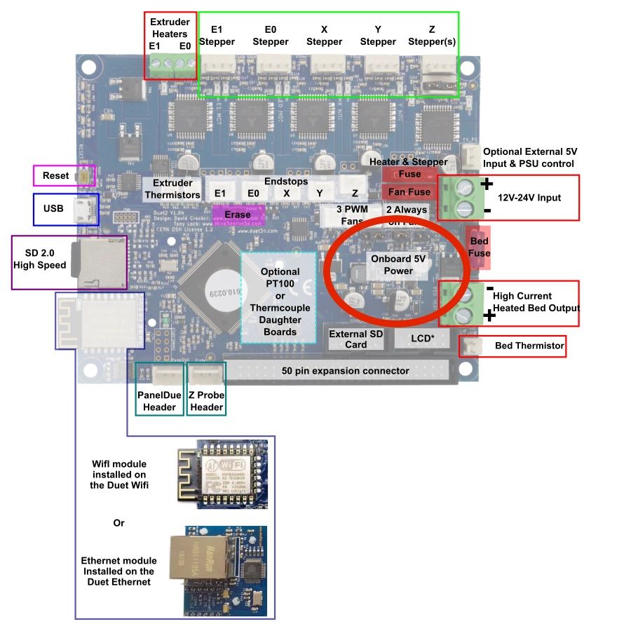
To detect possible damage of the 5V regulator, post a good-quality image of the encircled region of the board, labelled „Onboard 5V Power“:
-
@infiniteloop thank you, I will measure the bed leveling servo circuit, I suspect that it gives an overcurrent (opening and shorting). The 5V power rail may have been damaged because of this. I hope this means the death of the board

where is the function of these jumpers explained in more detail? See picture:
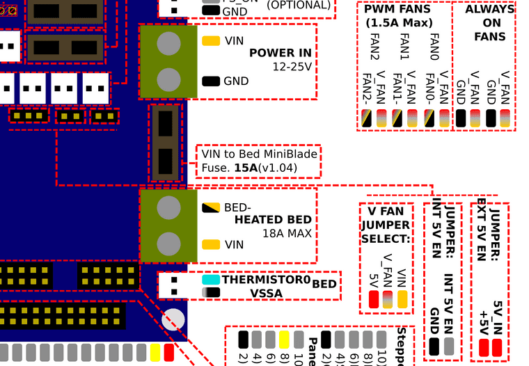
Thanks,
Jr -
where is the function of these jumpers explained in more detail?
See Wiring your Duet 2 mainboard, section 20: External 5V input and power supply control.