Multiple beds/chambers... bug?
-
I noticed some raised eyebrows here and there, when some users wanted multiple heaters, programmable, showing in DWC and Panel Due.
Still, this is a valid and important issue: one may need multiple items like those, or alike.
Yesterday I tried to use a water chiller, programmable, for on my 6XD/3HC printer.
It did not succed, because of many understanding issues, and meantime I gave up on this. Instead, I tried again today, with succes in setting a second chamber, for a filament dryer, a working one, I mean. So, if interested, can parse starting with POST 4. POST1 is, most of it, junk, but I let it so, if anyone wants to read it.
Finally, it seems I encountered some nasty BUG, even if I managed to make the filament dryer work... somehow.
-
@soare0 Sorry, no direct help but please can you edit your post to put the config file sections into code blocks? On my phone the button to add a code block is </> and it mades two sets of triple dashes appear. It will make it much easier to read.
This is what it appears like:
# Example M80 ... -
@DocTrucker Thanks for suggestion, it was welcomed, as I was asking myself about this... thing.
-
After some (more) reading and trying, I experimented with two possibilities:
-
Assigning the heater for filament box to T0 (in fact it is for it). Also, I took care to have sensor, output, etc, on the same board. In fact, I think all T0 is on that extension board
-
Making a separate heated chamber
Both seems to work, at first, but I like the 2nd better, and this is actual in (below) config.g.
Most of the problems, were due to coding errors, and insufficient understanding of the ”tool” concept.; Configuration file for Duet 3 MB 6XD (firmware version 3.3) ; executed by the firmware on start-up ; ; generated by RepRapFirmware Configuration Tool v3.4.0 on Wed Dec 20 2023 17:08:51 GMT+0200 (Eastern European Standard Time) ; General preferences M575 P1 S1 B57600 ; enable support for PanelDue G90 ; send absolute coordinates... M83 ; ...but relative extruder moves M550 P"AquaNano 3D" ; set printer name ; Wait a moment for the CAN expansion boards to start G4 S2 ; Network M551 P"paradis09" ; set password M552 P192.168.1.135 S1 ; enable network and set IP address M553 P255.255.255.0 ; set netmask M554 P192.168.1.1 ; set gateway M586 P0 S1 ; enable HTTP M586 P1 S0 ; disable FTP M586 P2 S0 ; disable Telnet ; Drives M569 P0.0 R0 S0 T5:5:10:0 ; X drive 0.0 goes forwards M569 P0.1 R0 S1 T5:5:10:0 ; Y drive 0.1 goes backwards M569 P0.2 R0 S1 T5:5:10:0 ; Z0 drive 0.2 goes backwards M569 P0.3 R0 S1 T5:5:10:0 ; Z1 drive 0.3 goes backwards M569 P0.4 R0 S1 T5:5:10:0 ; Z2 drive 0.4 goes backwards M569 P0.5 R0 S1 T5:5:10:0 ; Z3 drive 0.5 goes backwards M569 P1.0 R0 S0 T5:5:10:0 ; extruder drive 1.0 goes forwards M584 X0.0 Y0.1 Z0.2:0.3:0.4:0.5 E1.0 ; set drive mapping M671 X-70:-70:670:670 Y70:530:530:70 S0.5 ; POSITION OF LEADSCREW FRONT LEFT, RL, RR, FR M208 X0:550 Y0:600 ; Xcarriage move, Ycarriage move M92 X80.00 Y160.00 Z2400.00 E932 ; set steps per mm M566 X900.00 Y900.00 Z60.00 E120.00 ; set maximum instantaneous speed changes (mm/min) M203 X6000.00 Y6000.00 Z180.00 E1200.00 ; set maximum speeds (mm/min) M201 X500.00 Y500.00 Z20.00 E250.00 ; set accelerations (mm/s^2) M906 X3000 Y3000 Z3000 E1500 I30 ; set motor currents (mA) and motor idle factor in per cent M84 S30 ; Set idle timeout ; Axis Limits M208 X0 Y0 Z0 S1 ; set axis minima M208 X555 Y605 Z800 S0 ; set axis maxima ; Endstops M574 X1 S1 P"io1.in" ; configure switch-type (e.g. microswitch) endstop for low end on X via pin io1.in M574 Y1 S1 P"io2.in" ; configure switch-type (e.g. microswitch) endstop for low end on Y via pin io2.in M574 Z1 S2 ; configure Z-probe endstop for low end on Z ; Z-Probe M950 S0 C"io7.out" ; create servo pin 0 for BLTouch M558 P9 C"io7.in" H5 F120 T6000 ; set Z probe type to bltouch and the dive height + speeds G31 P500 X0 Y0 Z2.5 ; set Z probe trigger value, offset and trigger height M557 X50:550 Y50:550 S100 ; define mesh grid ; Heaters M308 S0 P"temp0" Y"thermistor" T100000 B4138 ; configure sensor 0 as thermistor on pin temp0 M950 H0 C"out0" T0 ; create bed heater output on out0 and map it to sensor 0 M307 H0 B1 S1.00 ; enable bang-bang mode for the bed heater and set PWM limit M140 H0 ; map heated bed to heater 0 M143 H0 S150 ; set temperature limit for heater 0 to 150C M308 S1 P"1.spi.cs0" Y"thermocouple-max31856" ; configure sensor 1 as thermocouple via CS pin 1.spi.cs0 M950 H1 C"1.out0" T1 ; create nozzle heater output on 1.out0 and map it to sensor 1 M307 H1 B0 S1.00 ; disable bang-bang mode for heater and set PWM limit M143 H1 S400 ; set temperature limit for heater 1 to 400C M308 S2 P"temp1" Y"pt1000" ; configure sensor 2 as pt1000 via temp1 M950 H2 C"out8" T2 ; create chamber heater output on out8 and map it to sensor 2 M307 H2 B1 S1.00 ; enable bang-bang mode for heater and set PWM limit M141 P0 H2 ; map chamber0 to heater 2 M143 H2 S80 ; set temperature limit for heater 2 to 80C M308 S3 P"1.temp2" Y"pt1000" A"Apa_E0" ; configure sensor 3 as pt1000 via 1.temp2 M308 S4 P"1.temp1" Y"thermistor" A"Fil_CH" ; configure sensor 4 as thermistor via 1.temp1 M950 H4 C"1.out1" T4 ; create filament heater output on 1.out7 and map it to sensor 4 M307 H4 B1 S1.00 ; enable bang-bang mode for heater and set PWM limit M141 P1 H4 ; map chamber1 to heater 4 M143 H4 S100 ; set temperature limit for heater 1 to 100C ; Fans M950 F0 C"1.out3" Q500 ; create fan 0 on pin 1.out3 and set its frequency. Ventilator racire cap, cu aer, nefolosit M106 P0 S1 C"Aer_E0" H1 T45 ; set fan 0 value. Thermostatic control is turned on M950 F1 C"1.out4" Q500 ; create fan 1 on pin 1.out4 and set its frequency M106 P1 S1 C"Piesa" H-1 ; set fan 1 value. Thermostatic control is turned off M950 F2 C"out7" Q500 ; create fan 2 on out7 and set its frequency M106 P2 S1 C"Camera" H2 T65 ; set fan 2 value. Thermostatic control senzor 2 is turned on. Ventilator racire camera, daca chiar o ia razna M950 F3 C"1.out6" Q500 ; create fan 3 on out6 and set its frequency M106 P3 S1 H1 T45 ; set fan 3 value. Thermostatic control senzor 1 is turned on. Motor circuit apa ;heaters fault detection M570 H2 P9999 T60 M570 H1 P9999 T90 M570 H0 P9999 T150 M570 H4 P9999 T100 ; Tools M563 P0 S"E0" D0 H1 F0:3:1 ; define tool 0 G10 P0 X0 Y0 Z0 ; set tool 0 axis offsets G10 P0 R0 S0 ; set initial tool 0 active and standby temperatures to 0C ; Filament sensors M591 P1 C"1.io0.in" S1 D0 ; define simple microsw fil sensor at bd 1 inp 0, low is fil runout M591 D0 P3 C"1.io1.in" S1 ; filament monitor magnetic ; Custom settings are not defined ; Miscellaneous M501 ; load saved parameters from non-volatile memory M911 S20 R22 P"M913 X0 Y0 G91 M83 G1 Z3 E-1 F1000" ; set voltage thresholds and actions to run on power loss T0 ;select first tool - commentedInteresting, if one uses heated chamber in Cura, parameters will be sent to slot 0. chamber, wich is ok - I was not so sure it will work, as I have not checked the output from Cura.
One thing though, the chamber (main chamber, slot 0, that is) will be heated the last (one would think that its heating it would be needed to be start first), but in fact, it is not quite so... at all. Most probably there is a setting for heating order. For now, it is bed/nozzle/chamber, I still need to check where too look for.
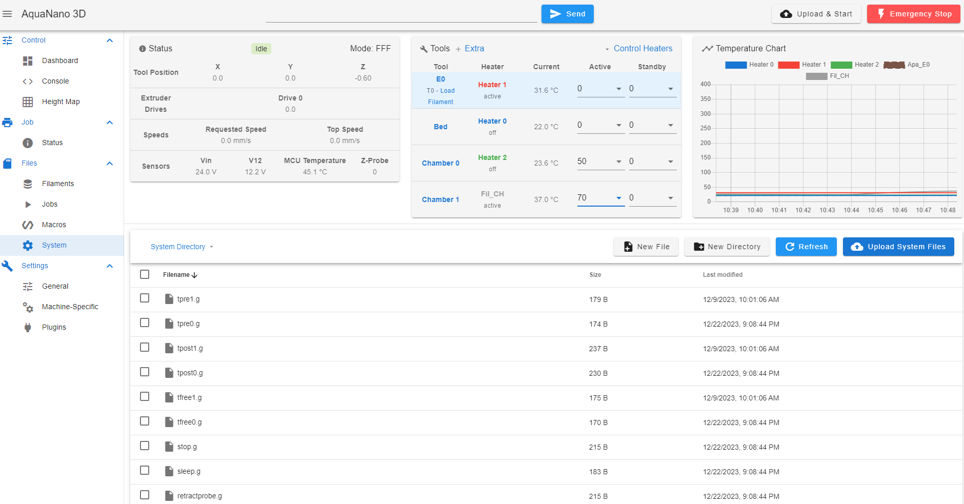
Chambers shows ok in DWC:
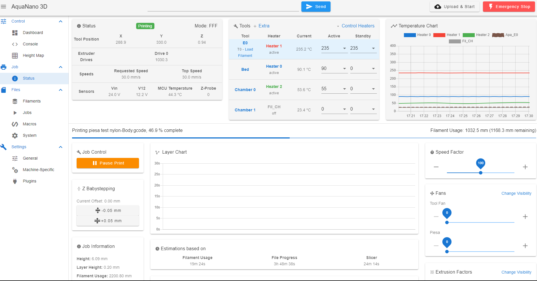
Also they are showing ok in Panel Due.
Tomorrow we will connect PTCs, and do a test.
-
-
@soare0 Starting testing the filament dryer, I connected the PTCs, and ... start testing.
In DWC, all is ok. One can programm filament roll chamber, and it works well.
One can see that the chamber started heating, and all is ok.
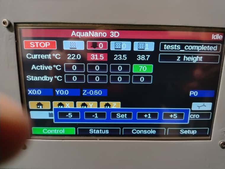
HOWEVER, there seems to be a problem with Panel Due (I mean, maybe not with it, but with my 6XD, but it is shown there).
When setting active temperature for SLOT1 chamber, that is filament chamber, wich is the left one in the image, the settings will transfer to SLOT0 chamber, wich is the right one, the printing chamber.
In image 1 one can see setting the active temperature for chamber 1, and in image 2, one can see... the unexpected result: the setting is transferred to chamber 0, wich, well... starts heating!
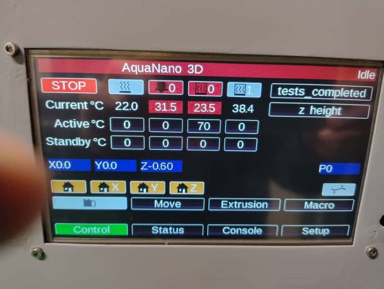
Please understand: It is unlikely to have a coding problem here, in my .g files, as it works from DWC, at least this is my understanding of the system, now.
BUGBUGBUGBUGBUGBUGBUG
bug? -
@soare0 Yes, it was a bug in 3.4.6.
I updated all the boards to 3.5.0/1 rc2, and for now, all works.Thanks for all.