6HC inductive 4 wire endstop wiring
-
Hi,
I am using pepperl & fuchs inductive endstops (NBN4-F29-A2
) and haven't been able to get them working. They're 5v sensor. So I wired them to th IO ext5 pin and tried both the normally open and closed contact to the input. But I haven't been able to 'trigger' them in the software. I see them working (LED indicator) but a no point have I been able to use them in software. I tried using the Object model plugin but they never switch states.
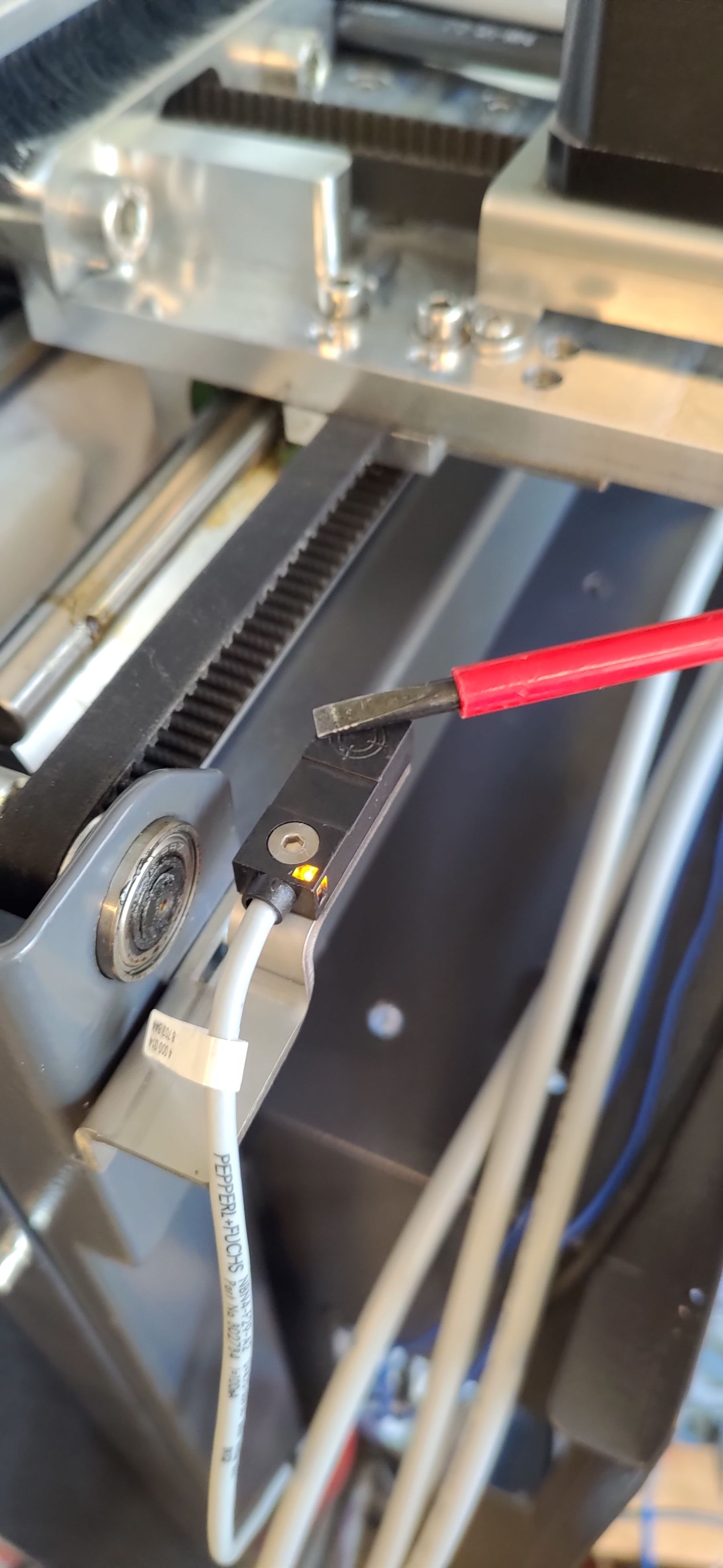
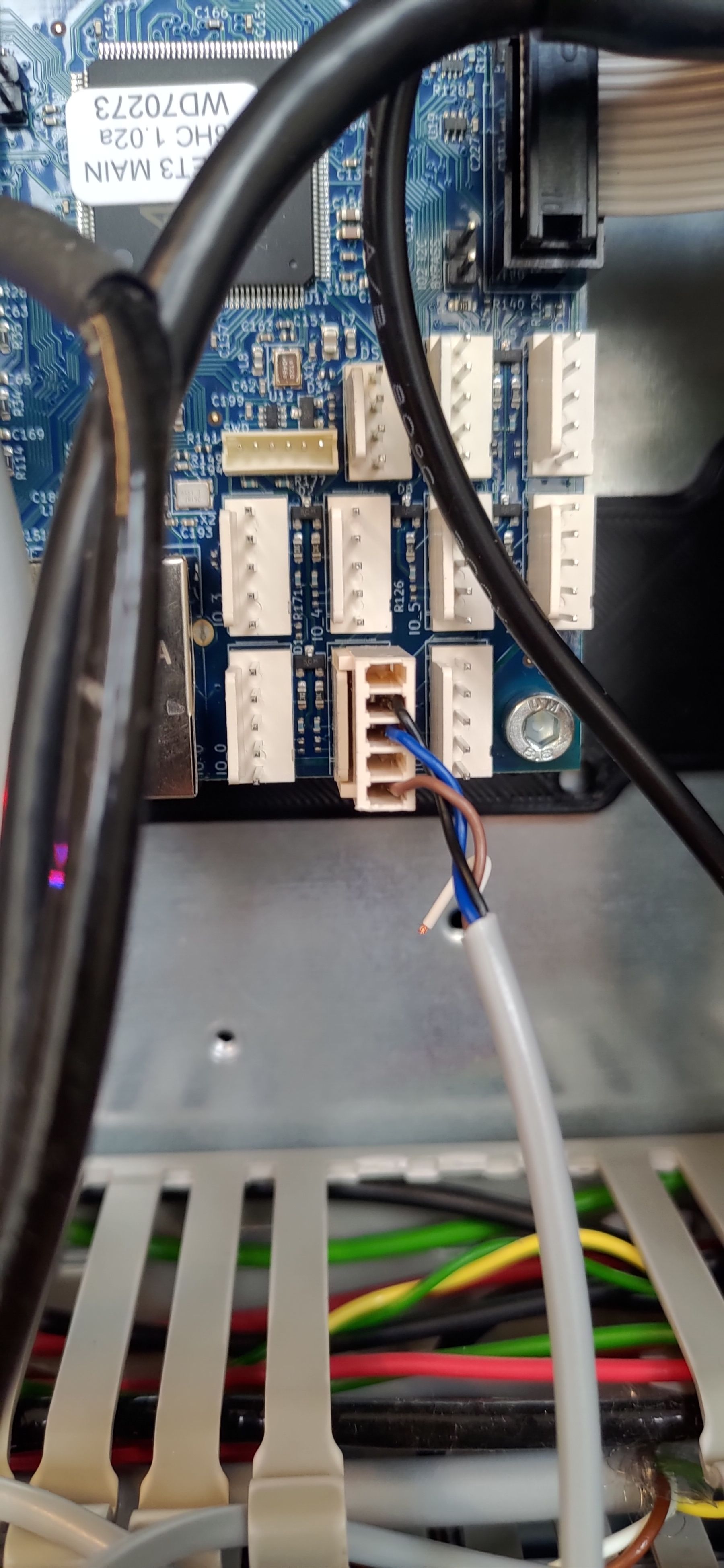
I have 3 of them, one for each axis, only one is plugged in the picture```Am I missing something? The NO802784_eng.pdf contact is around 3,2V (between ground) when not triggered, and 5V when trigger). Is 3,2 V to high causing them to always be active? Note: config.g is incomplete, I'm configuring it step by step to troubleshoot it.
; Configuration file for RepRapFirmware on Duet 3 Main Board 6HC ; executed by the firmware on start-up ; ; generated by RepRapFirmware Configuration Tool v3.5.0-rc.2+6 on Wed Jan 24 2024 15:15:05 GMT+0100 (Midden-Europese standaardtijd) ; General M550 P"Duet 3" ; set hostname ; Network M552 P0.0.0.0 S1 ; configure Ethernet adapter M586 P0 S1 ; configure HTTP ; Smart Drivers M569 P0.0 S0 D2 ; driver 0.0 goes backwards (X axis) M569 P0.1 S0 D2 ; driver 0.1 goes backwards (Y axis) M569 P0.2 S0 D2 ; driver 0.2 goes backwards (Z axis) M569 P0.3 S1 D2 ; driver 0.3 goes forwards (extruder 0) ; Motor Idle Current Reduction M906 I30 ; set motor current idle factor M84 S30 ; set motor current idle timeout ; Axes M584 X0.0 Y0.1 Z0.2 ; set axis mapping M350 X16 Y16 Z16 I1 ; configure microstepping with interpolation M906 X1600 Y2200 Z2400 ; set axis driver currents M92 X64 Y80 Z400 ; configure steps per mm M208 X0:400 Y0:400 Z0:400 ; set minimum and maximum axis limits M566 X900 Y900 Z12 ; set maximum instantaneous speed changes (mm/min) M203 X6000 Y6000 Z180 ; set maximum speeds (mm/min) M201 X500 Y500 Z20 ; set accelerations (mm/s^2) ; Extruders M584 E0.3 ; set extruder mapping M350 E16 I1 ; configure microstepping with interpolation M906 E1200 ; set extruder driver currents M92 E420 ; configure steps per mm M566 E120 ; set maximum instantaneous speed changes (mm/min) M203 E3600 ; set maximum speeds (mm/min) M201 E250 ; set accelerations (mm/s^2) ; Kinematics M669 K0 ; configure Cartesian kinematics ; Endstops M574 X1 P"!io0.in" S1 ; configure X axis endstop M574 Y1 P"!io1.in" S1 ; configure Y axis endstop M574 Z2 P"!io3.in" S1 ; configure Z axis endstop ; Sensors M308 S0 P"temp0" Y"thermistor" A"Heated Bed" T100000 B4725 C7.06e-8 ; configure sensor #0 M308 S1 P"temp1" Y"thermistor" A"Nozzle" T100000 B4725 C7.06e-8 ; configure sensor #1 ; Heaters M950 H0 C"out0" T0 ; create heater #0 M143 H0 P0 T0 C0 S140 A0 ; configure heater monitor #0 for heater #0 M307 H0 R2.43 D5.5 E1.35 K0.56 B1 ; configure model of heater #0 M950 H1 C"out1" T1 ; create heater #1 M143 H1 P0 T1 C0 S285 A0 ; configure heater monitor #0 for heater #1 M307 H1 R2.43 D5.5 E1.35 K0.56 B0 ; configure model of heater #1 ; Heated beds M140 P0 H0 ; configure heated bed #0 ; Fans M950 F0 C"out3" ; create fan #0 M106 P0 S0 L0 X1 B0.1 ; configure fan #0 M950 F1 C"out4" ; create fan #1 M106 P1 S0 B0.1 H1 T45 ; configure fan #1 ; Tools M563 P0 H1 F0 ; create tool #0 M568 P0 R0 S0 ; set initial tool #0 active and standby temperatures to 0C ; Miscellaneous M501 ; load saved parameters from non-volatile memory code_text -
@DieterSw said in 6HC inductive 4 wire endstop wiring:
NBN4-F29-A2
the data sheet would indicate that you are possibly wired up incorrectly
the data sheet shows
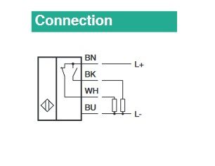
it looks like your black wire is wrong and it looks like you should be using white instead of blue
-
I would say that 3.2 is too high. Possibly a resistor from the input to ground could reduce that voltage to a suitable level.
Do they have a NPN version?
Frederick
-
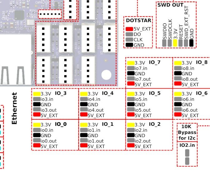
@Mr-Crispin Why do you think that? I connected BN to 5V_EXT, BU to GND. And BK to iO.in. I might switch black/white to use the NO closed contact but the rest seems correct I think?
-
@DieterSw said in 6HC inductive 4 wire endstop wiring:
@Mr-Crispin Why do you think that? I connected BN to 5V_EXT, BU to GND. And BK to iO.in. I might switch black/white to use the NO closed contact but the rest seems correct I think?
ok then apply logic.
The wiring diagram from the data sheet shows a different way from what you have
You are wired differently/incorrectly according to the duet docs
(The most glaringly obvious one) IT'S NOT WORKING FOR YOU in its current configuration
Ask yourself why.
-
@DieterSw said in 6HC inductive 4 wire endstop wiring:
@Mr-Crispin Why do you think that? I connected BN to 5V_EXT, BU to GND. And BK to iO.in. I might switch black/white to use the NO closed contact but the rest seems correct I think?
Aside from the issue of the signal level being invalid you have it wired correctly in regards to what wires are going where.
I don't know that switching to the NO connection would change the signal level.
If memory serves me I went with NPN devices (rather the PNP) just for this signal level problem. I also remember during testing creating a voltage divider using two resistors to get a suitable signal level.
Frederick
-
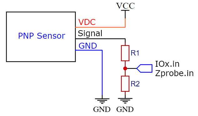
@DieterSw For a PNP device, see the example here for how to connect: https://docs.duet3d.com/User_manual/Connecting_hardware/Z_probe_connecting#pnp-output-normally-open-inductive-or-capacitive-sensor
I've added a wiring diagram to make it clearer how to wire a PNP sensor. See above text for values for R1 and R2.
Ian