Duet3 Mini5+ FAN pin behavior at power lost
-
I'm bench-testing my laser rig using Duet3 Mini5+.
I've...
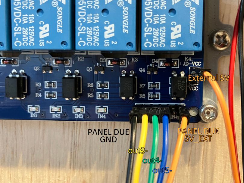
[out6_buffer] === PWM-to-Analog converter for 0~10V laser power single[PANEL DUE GND] === Relay board [GND]
[PANEL DUE 5V_EXT] === Relay board [VCC]
[out3-] === Relay board [IN1]
[out4-] === Relay board [IN2]
[out5-] === Relay board [IN3]
[External 5V] === Relay board [JD-VCC], to power the coilAnd in config.g I've...
; Laser mode
M452 C"out6" R255 F200 ; Enable Laser mode, on out6, with max intensity being 255, and a PWM frequency of 200

; FAN-as-IO setup
M950 P0 C"out3" ; Red Laser
M950 P1 C"out4" ; Laser Enable
M950 P2 C"out5" ; placeholder
The bench-testing (not wiring to actual laser) seems ok. M42 P0 S1 enable IN1 relay, and M42 P0 S0 disable IN1 relay. P1/P2 also doing the same thing, which is good.
However, at power lost (ex: unplug Duet3), between [out3-] and [PANEL DUE 5V_EXT] will jump from 0V to ~2.7V and slowly bleeding away. While it's not enough to trigger relay, it's there. Same case for [out4-], [out5-].
Is there way to ensure that, at power lost, it stay at 0V ? As I plan to switch to MOSFET later.
(edit: better writing to avoid confusion)
-
Add note...
I've 24V and 5V PSU -V connected together in the previous testing.
I also did following testing:
##Not using external 5V PSU##
[PANEL DUE 5V_EXT] === Relay board VCC
[out3-] === Relay board [IN1][PANEL DUE 5V_EXT] === Relay board JD-VCC (powering relay coil with Duet's onboard 5V)
[PANEL DUE GND] === Relay board [GND]
##Isolate 5V PSU##
Not connecting 24V and 5V PSU's -V together.[PANEL DUE 5V_EXT] === Relay board VCC
[out3-] === Relay board [IN1]External 5V PSU [+V] === Relay board JD-VCC
External 5V PSU [-V] === Relay board [GND]
In both scenario, at power lost, there is ~2.7V between [out3-] and [PANEL DUEL 5V_EXT], same as original setup.
-
@titusou you can add an external pulldown resistor of say (4k7) to the pin.
-
@T3P3Tony
You mean in series between Duet and relay board? -
@titusou no between the pin and ground.
-
@T3P3Tony I managed to get this work by...
[PANEL DUE 5V_EXT] === Relay board VCC
[PANEL DUE 5V_EXT] === 4.7K Ohm === [24V PSU -V]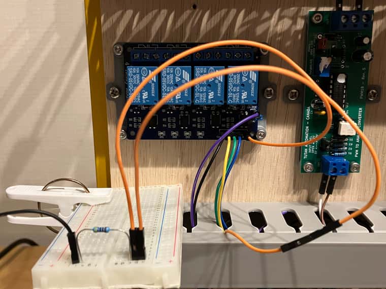
If I do...
[out3-] === Relay board [IN1]
[out3-] === 4.7K Ohm === [24V PSU -V]
The relay will enable when powerup, and remain on when power lost for a long time (probably until PSU completely dry)Did I do something odd?
Thanks in advance!
-
@titusou said in Duet3 Mini5+ FAN pin behavior at power lost:
[PANEL DUE 5V_EXT] === 4.7K Ohm === [24V PSU -V]
interesting so you are draining the capacitance on the 5V supply via that resistor.
Presumably the relay board V- is connected to proper ground? -
@T3P3Tony I'm currently have 5V PSU connected as isolated supply to the relay coil
So on the signal side there is really no GND.
Is this going to cause some odd problem? Draining the board instead of pulldown signal?
-
@titusou ok connect the grounds together otherwise you will have issues with stuff loating to different levels - as you are seeing.
-
@T3P3Tony Still acting odd...
I now have...
No external 5V PSU, all power by Duet's 5V.
Duet [PANEL DUE 5V_EXT] === Relay board [VCC], which jumper connect to [JD-VCC] to power coil
Duet [GND] === 24V PSU [-V] === Relay [GND]
Duet [out3-] === Relay board [IN1]
Duet [out3-] === 4.7K Ohm === 24V PSU [-V]And relay enabled as soon as power on.
I check the relay board's schematic, and I think it's neg-side-controlled. So having pull-down on the [IN1] actually ground the [IN1] and cause it enable instantly at powerup.
So if that the case, having pull-down on the [VCC] is actually kind correct?
-
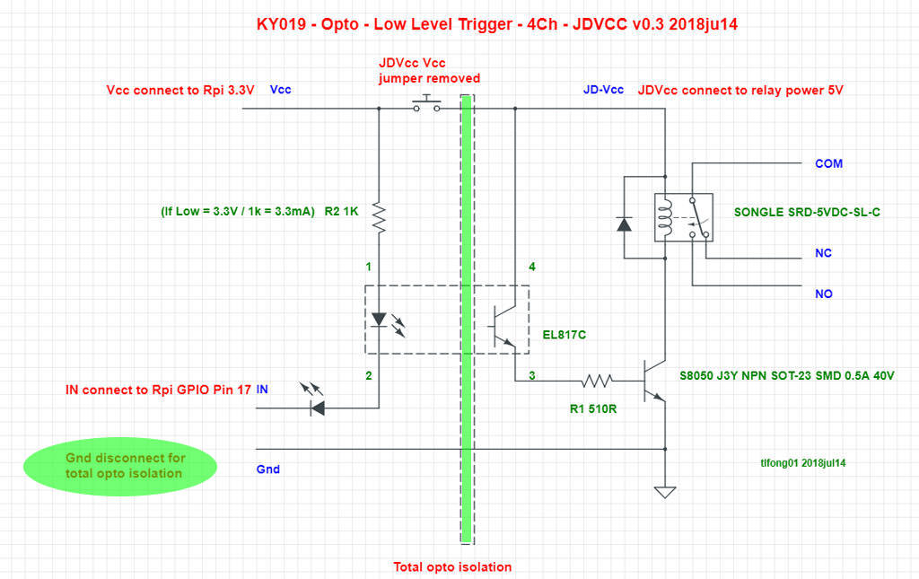
@titusou
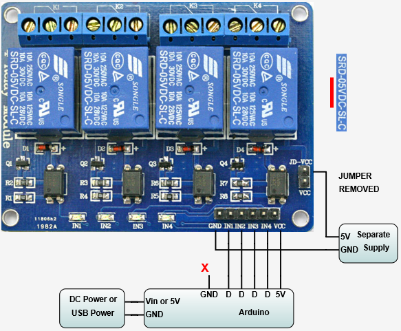
Referring to the KY019 schematics and the image above, you need to separate the logic level (3.3V) from both the input voltage the relay requires (5.0V) and the relays-controlled voltage (24.0V). With the JD-Vcc jumper in place (as spotted in the photo), the logic level requires 5.0V, which will not work, as the Duet-I/O uses 3.3V instead.Remove the jumper JD-Vcc, feed 3.3V from the Duet into Vcc (labelled ”Vcc connect to Rai 3.3V”), feed 5.0V into JD-Vcc (labelled ”JDVcc connect to relay power 5V”). Possibly, you can forget about the pull-down resistor.
Oh, and don’t waste any further thought on whether or not to connect the V- of your PSUs: They need a common GND.
-
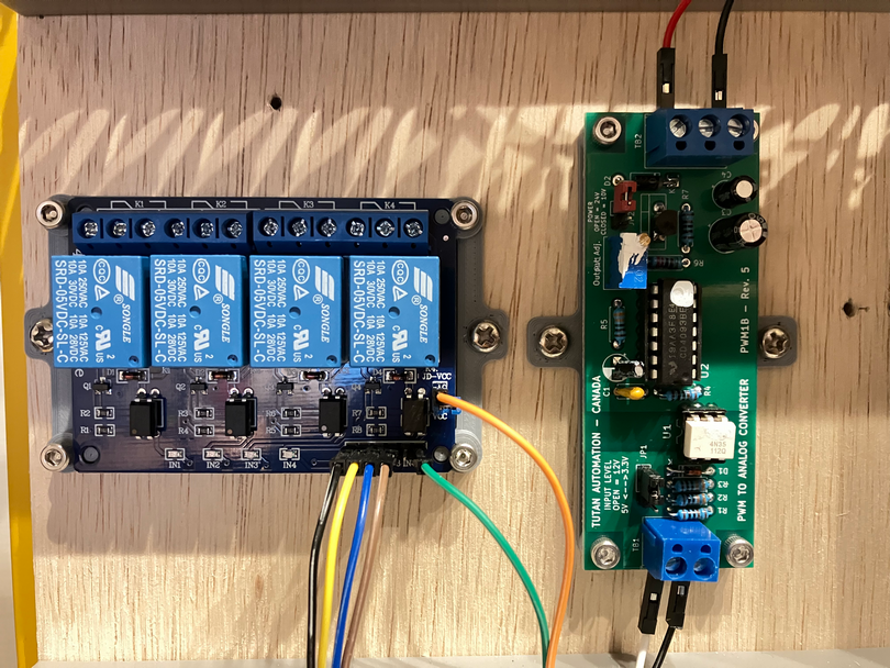
@infiniteloop I got it works as you described. Thank you!!!
Some detail for future reference.
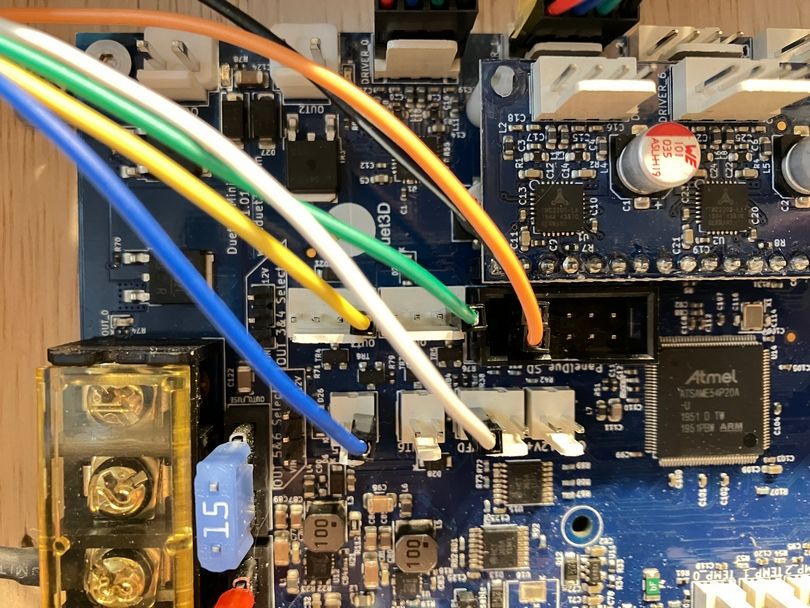
Duet [PANEL DUE 5V_EXT] ==(orange)== Relay [JD-VCC]
Duet [PANEL DUE 3.3V_EXT] ==(green)== Relay [VCC]
Duet [PANEL DUE GND] ==(black)== Relay [GND]
Duet [out3-] ==(yellow)== Relay [IN1]
Duet [out4-] ==(blue)== Relay [IN2]
Duet [out5-] ==(brown)== Relay [IN3]
config.g
; Laser mode
M452 C"out6" R255 F200 ; Enable Laser mode, on out6, with max intensity being 255, and a PWM frequency of 200

; FAN-as-IO setup
M950 P0 C"out3" ; Red Laser
M950 P1 C"out4" ; Laser Enable
M950 P2 C"out5" ; placeholder
No strange behavior during power on nor power lost. Everything looks good.
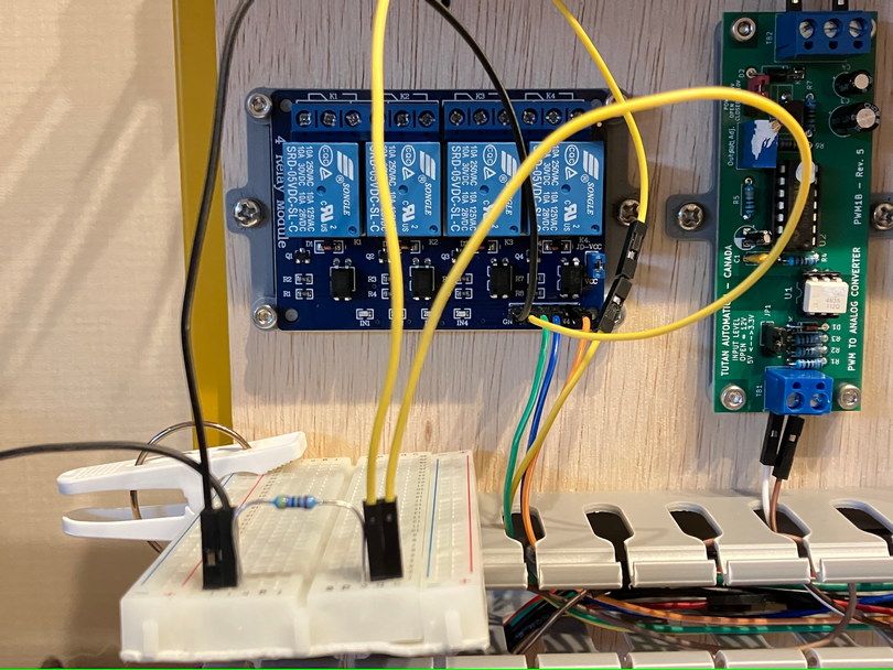
Note: the board next to relay is isolated PWN to 0-10V converter, in case someone wondering.