Duet 2 WiFi Warranty Claim
-
Hello all,
I have been using the Duet 2 WiFi board for the Modix Big 60 V3 printer. I have been running into some issues that seem to all lead back to the board. I just replaced the board only four months ago as this issue happened before.
All was going well for a few weeks with the new board and then I started getting some Driver out of phase errors. Thinking it was a wiring problem, I replaced all the wires and connectors for the motors and all seemed well. I noticed that one of the pins on the board side for Driver 1 had melted a little. Not entirely sure what caused this precisely. I doube checked that nothing had been shorted and all work had been done while the machine was completely powered off.
Once these wires had been fixed a new issue arose upon turning the machine back on. I was now getting a thermistor disconnect error and the sensors were reading 2000deg. I tested the wires for continuity and got good continuity. I tested the terhmistors resistance and got the expected values. Then I tested the voltage across the two thermistor pins and got 0V. Clearly something on the board has been shorted or disconnected. I have checked the board for any damage and there is no visible damage on the top or underside.
The driver out of phase issue has been a recurring issue that pops up once every couple of weeks and goes away with new connectors or wiring (frustrating). Clearly, there is something else going on that keeps causing this issue to reoccur.
I have added the config.g file for convenience.
config.g
; Modix Big-60, Duet, Dual Printhead
; Configuration file for Duet WiFi (firmware version 3.4.5)
; Generated by Modix - Version 3.4.5 Config B
global config_version = "Version 3.4.5 Config B"
global generation = 3 ; Generation 3 printer
global printhead = 1 ; Griffin printhead
global expansion = 0 ; no expansion board is installed
global printheads = 2 ; Dual printhead, change this value to 1 to switch it to a single-printhead setup
global idex = 0 ; no IDEX; General preferences_________________________________________________________
G90 ; send absolute coordinates...
M83 ; ...but relative extruder moves
M555 P2 ; Set output to look like Marlin
M575 P1 B57600 S1 ; Set auxiliary serial port baud rate and require checksum (for PanelDue); Network_____________________________________________________________________
M550 P"Big 60" ; set printer name
;M551 P"MODIX3D" ; Set password (optional)
M98 P"config_networking.g" ; load networking settings
G4 P300 ; wait 300ms
;M552 P0.0.0.0 ; Uncomment this command for using Duet Ethernet board; Drives_________________________________________________________________________
M569 P0 S1 ; Physical drive 0. X-Axis
M569 P1 S0 ; Physical drive 1. Y-Axis
M569 P2 S0 ; Physical drive 2. Z-Axis
M569 P3 S0 ; Physical drive 3. Primary Extruder
M569 P4 S0 ; Physical drive 4. Secondary Extruder;Motor to stepper motor driver mapping_________________________________________________________
M584 X0 Y1 Z2 E3:4 P3 ; Driver mapping;Motor settings and acceleration limits___________________________________________________________________
M350 X16 Y16 Z16 E16:16 I1 ; Configure microstepping with interpolation
M92 X100 Y100 Z2000 E418.5:418.5 ; Set steps per mm
M566 X360 Y360 Z30 E3000:3000 P1 ; Set maximum instantaneous speed changes (mm/min)
M203 X9000 Y9000 Z400 E6000:6000 ; Set maximum speeds (mm/min)
M201 X1000 Y1000 Z200 E5000:5000 ; Set accelerations (mm/s^2)
M204 P500 T1000 ; Set print and travel accelerations (mm/s^2)
M906 X1800 Y1800 E1000:1000 Z2300 I50 ; Set motor currents (mA) and motor idle factor in per cent
M84 S100 ; Set idle timeout - 100 seconds; Axis Limits
M208 X0 Y0 Z-3 S1 ; set axis minima
M208 X600 Y600 Z660 S0 ; set axis maxima; Endstops
M574 X1 S1 P"xstop" ; configure switch-type (e.g. microswitch) endstop for low end on X via pin xstop
M574 Y2 S1 P"ystop" ; configure switch-type (e.g. microswitch) endstop for low end on Y via pin ystop; Z-Probe
M558 P9 C"zprobe.in" H4 F180 T9000 R0.5 ; BLTouch probing settings
M950 S0 C"exp.heater3" ; set probe pin
M376 H100 ; Height (mm) over which to taper off the bed compensation
G31 P500 X-25.5 Y26.9 ; BLTouch X and Y offset
M557 X{move.axes[0].min + sensors.probes[0].offsets[0] + 1, move.axes[0].max + sensors.probes[0].offsets[0] - 1} Y{move.axes[1].min + sensors.probes[0].offsets[1] + 1, move.axes[1].max + sensors.probes[0].offsets[1] - 1} P10:10
; The M557 is used to define the mesh grid area. It uses the P parameter to set the amount of probing points. P10:10 would be a 10x10 grid. Supports up to a 21x21 grid.
M98 P"config_probe.g" ; Load the Z-offset from the config_probe.g file
; The Z_offset value is now set in config_probe.g, not in config.g
; Adjust the values there, do not adjust anything here.; Heaters___________________________________________________________
M140 H-1 ; disable heated bed (overrides default heater mapping);E0_________________________________________________________________
;M308 S0 P"e0temp" Y"thermistor" T100000 B4725 C7.06e-8 ; configure sensor 0 as thermistor on pin e0temp
;M308 S0 P"spi.cs1" Y"rtd-max31865" ; Configure sensor 0 as PT100 via the daughterboard
M308 S0 P"e0temp" Y"pt1000" ; Configure sensor 0 as PT1000 on pin e0temp
M950 H0 C"e0heat" T0 ; create nozzle heater output on e0heat and map it to sensor 0
M98 P"PID_tune_E0.g" R1 ; PID calibration
; M307 is not used in this config. The M307 files are stored and executed from the PID_tune_E0.g file. You can verify the values there.
M143 H0 S285 ; set temperature limit for heater 0 to 285Cif {global.printheads} = 2
;E1_________________________________________________________________
;M308 S1 P"e1temp" Y"thermistor" T100000 B4725 C7.06e-8 ; configure sensor 1 as thermistor on pin e1temp
;M308 S1 P"spi.cs2" Y"rtd-max31865" ; Configure sensor 1 as PT100 via the daughterboard
M308 S1 P"e1temp" Y"pt1000" ; Configure sensor 1 as PT1000 on pin e1temp
M950 H1 C"e1heat" T1 ; create nozzle heater output on e1heat and map it to sensor 1
M98 P"PID_tune_E1.g" R1 ; PID calibration
; M307 is not used in this config. The M307 files are stored and executed from the PID_tune_E1.g file. You can verify the values there.
M143 H1 S285 ; set temperature limit for heater 1 to 285C; Fans & LED_________________________________________________________
M950 F0 C"fan0" Q500 ; create fan 0 on pin fan0 and set its frequency
M106 P0 S0 H-1 C"Primary blower fan" ; set fan 0 value.
M950 F2 C"fan2" Q500 ; create LED on pin fan2 and set its frequency
M106 P2 S0 H-1 C"LED" ; Disable fan channel for LEDif {global.printheads} = 2
M950 F1 C"fan1" Q500 ; create fan 1 on pin fan1 and set its frequency
M106 P1 S0 H-1 C"Secondary blower fan" ; set fan 1 value.; Tools______________________________________________________________
;T0_________________________________________________________________
M563 P0 S"E0 Primary" D0 H0 F0 ; define tool 0
G10 P0 X0 Y0 Z0 ; set tool 0 axis offsets
G10 P0 R0 S210 ; set initial tool 0 active and standby temperatures to 0Cif {global.printheads} = 2
;T1_________________________________________________________________
M563 P1 S"E1 Secondary" D1 H1 F1 ; define tool 1
G10 P1 X0 Y74.3 Z0 ; set tool 1 axis offsets
G10 P1 R0 S210 ; set initial tool 1 active and standby temperatures to 0C; Automatic power saving____________________________________________
M911 S22.5 R29.0 P"M913 X0 Y0 G91 M83 G1 Z3 E-5 F1000" ; Set voltage thresholds and actions to run on power loss. Power Failure Pause; Filament sensor settings__________________________________________________
;M591 D0 P1 C"e0stop" S1 ; Regular filament sensor forE0
;M591 D1 P1 C"e1stop" S1 ; Regular filament sensor forE1; Add-on settings__________________________________________________
; Primary hotend Clog detector__________________________________________________
M591 D0 P7 C"e0stop" S1 L3.2 E10 R10:300 ; Clog Detector E0 [Add-On];Secondary hotend Clog detector__________________________________________________
M591 D1 P7 C"e1stop" S1 L3.2 E10 R10:300 ; Clog Detector E1 [Add-On]; Crash detector__________________________________________________
;M950 J2 C"zstop" ; create Input Pin 2 on Z-endstop to for M581 Command.
;M581 P2 T0 S0 R0 ; Crash Detector [Add-On]; Emergency stop button__________________________________________________
;M950 J3 C"exp.e6stop" ; create Input Pin 2 on pin E6 to for M581 Command.
;M581 P3 T0 S1 R0 ; Emergency stop [Add-On]
;M581 P3 T1 S1 R1 ; Emergency stop, pause the print [Add-On]
;M581 P3 T1 S1 R0 ; Emergency stop, pause always [Add-On]; Automatic Z Offset Calibration____________________________________
M574 Z1 S1 P"^!connlcd.enca" ; configure switch-type for Automatic z-offset
;M501 -
@chris-costa Hm. What did the MODIX support tell you?
-
@infiniteloop They said it was likely an issue with the motors themselves for the first problem. I have checked the motors and they all work properly and as expected.
The thermistor issue they said was likely a board issue based on the same reasons I mentioned earlier.
-
@chris-costa To lower your expectations: I’m in no way a Modix expert. Here’s what I have to say despite that.
The Duet2 is not known to be a short-lived product. Ok, every board (or one of its components) can somehow fail, but if the ”out of phase error” sneaks in with a replacement board as well, the reason for this should probably be located elsewhere. Modix support seems to think into the same direction:
They said it was likely an issue with the motors themselves for the first problem.
To probe this theory, you should - temporarily - replace the stepper in question. BTW: is it always the same motor, or are multiple axes involved?
In the config.g, there seems nothing to be obviously wrong. Well, Modix calls some macros which I can’t look into, but these don’t affect the motors. However, the current of the Z stepper is near the limits of what the Duet2 can handle: at 2300 mA, active cooling of the board is definitely required. But that’s a question Modix has to clarify.
If the errors disappear for a while after rewiring, If then, as you further explain, you noticed this here:
one of the pins on the board side for Driver 1 had melted a little.
… Then I can imagine that there are some unintended high currents around: I can’t tell for sure, but improper grounding is one of the suspects to look at.
As for the thermistors: Maybe they are part of the same game - if I’m not completely wrong, a considerable amount of current desperately looks for some appropriate wiring to somehow reach the Duet.
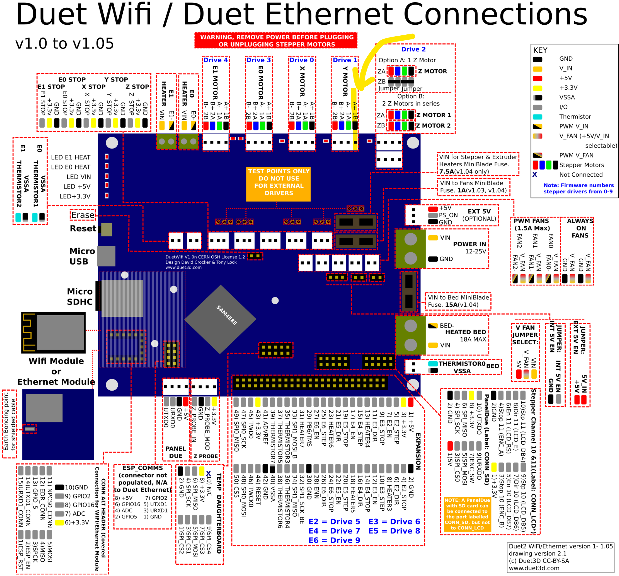
From a distance and without intimate knowledge of the Modix printers, I’m unable to assist in resolving the issue, but in order for more capable 'long distance experts' to step in, it could be helpful to precisely locate the above mentioned pin which had melted a little. You can use this diagram to mark that pin.
-
@chris-costa said in Duet 2 WiFi Warranty Claim:
I just replaced the board only four months ago as this issue happened before.
Was that a warranty replacement board?
-
@chris-costa said in Duet 2 WiFi Warranty Claim:
All was going well for a few weeks with the new board and then I started getting some Driver out of phase errors.
"Out of phase" is not a message from RepRapFirmware. What is the exact message?
I noticed that one of the pins on the board side for Driver 1 had melted a little.
That suggests to me that either the solder joint on that pin is bad, or there was a poor crimp connection of the wire plugged onto that pin - in which the plug would likely show scorch marks around that pin too. In either case RRF would likely have reported "Driver 1 phase A may be disconnected" or a similar message about phase B.
Duet WiFi hardware designer and firmware engineer
Please do not ask me for Duet support via PM or email, use the forum
http://www.escher3d.com, https://miscsolutions.wordpress.com -
@Phaedrux said in Duet 2 WiFi Warranty Claim:
Was that a warranty replacement board?
No
@dc42 said in Duet 2 WiFi Warranty Claim:
RRF would likely have reported "Driver 1 phase A may be disconnected" or a similar message about phase B.
Yes, the error reported is "Driver 1 phase A may be disconnected"I had just replaced the crimps and checked all wires for continuity before plugging everything back in. It then happened again, which leads me to believe it is a board issue.
-
@infiniteloop said in Duet 2 WiFi Warranty Claim:
it could be helpful to precisely locate the above mentioned pin which had melted a little
It was the pin in this image. Pin 1B on Drive 1.
-
@chris-costa said in Duet 2 WiFi Warranty Claim:
Was that a warranty replacement board?
No
Where and when was the replacement board purchased?
Have you replaced the motor for the driver that has been giving the issue?