tevo little monster duet wifi
-
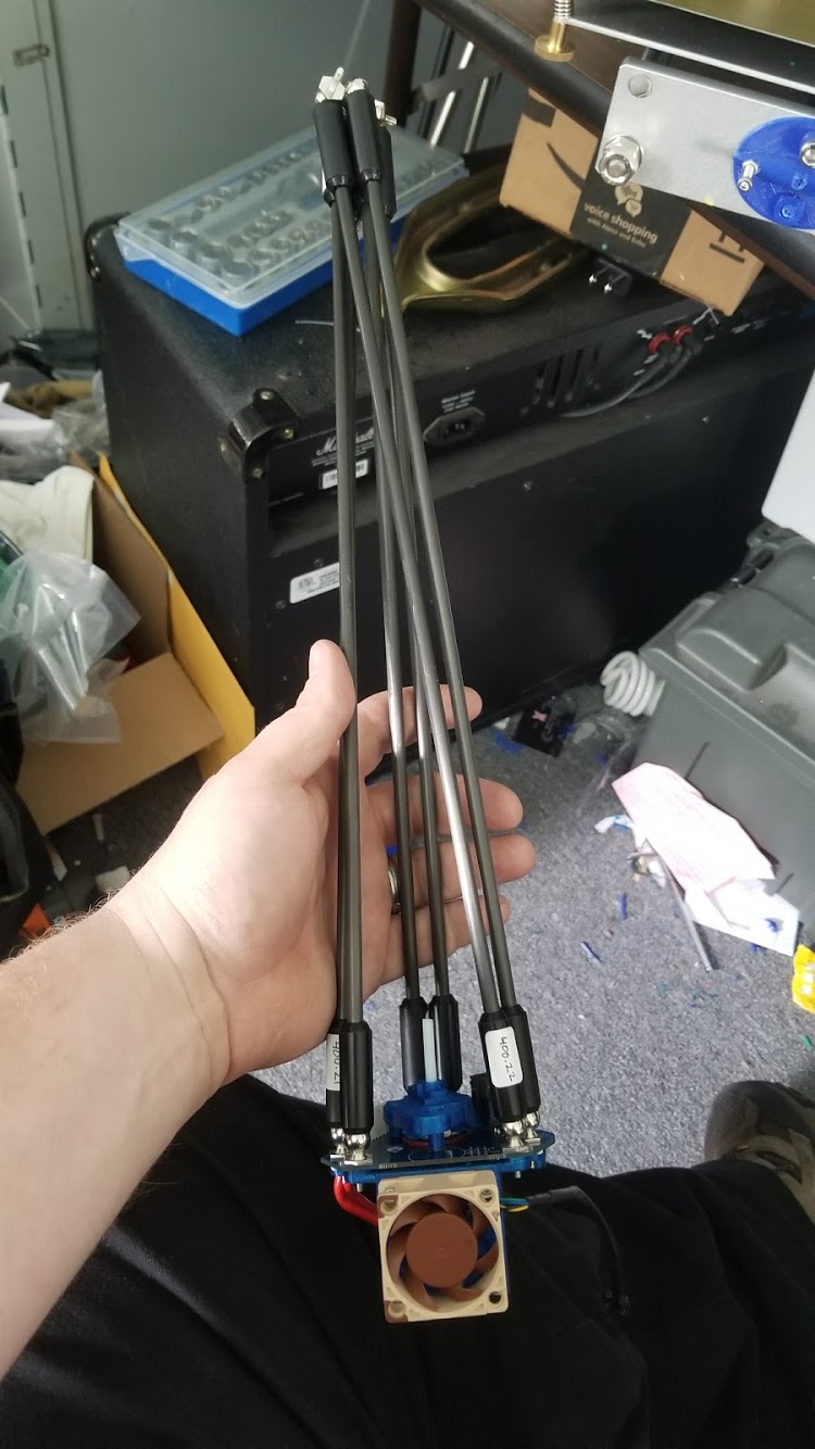
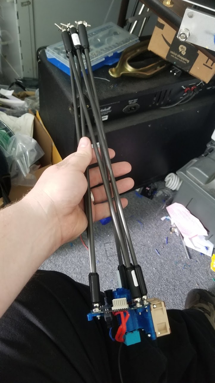
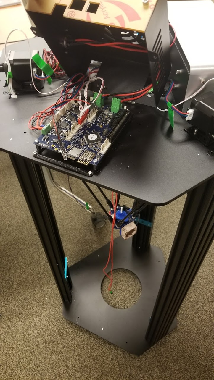
interesting you cant see the pics. they are links from my google photos. they are just of the smart effector with hayden rods and the duet bord.
dose the wifi server version look correct to you?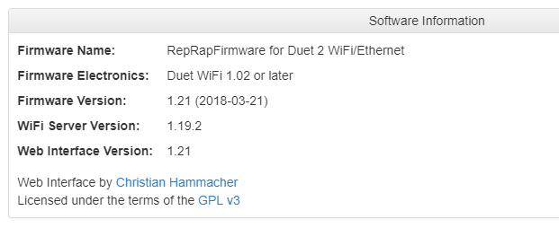
ok so let me see if i got the fan thing correct.
i have a 24v power supply and a 24v berdair pump. i hook the positive and groun up to one of the pwm headers on the bord
the 12v 40mm noctua i use a buck converter and get 24v power form one of the always on fan header, then down grade to 12 v and send just the the positive to the fan. then i hook the pwm and ground to a pwm header. do i hook the ground to ground and the pwm to positive? -
also for whiring i was wondering if you though using some cat6 eathernet cable would be ok for hookup on the thermsistor, fan power, and the probe? i also have some 2 pin wire 18ga copper clad aluminum i was going to use for the hotend heater power. it says its rated for 24v
-
@bendiesel said in tevo little monster duet wifi:
dose the wifi server version look correct to you?
No, it should be 1.21.
ok so let me see if i got the fan thing correct.
i have a 24v power supply and a 24v berdair pump. i hook the positive and groun up to one of the pwm headers on the bord
the 12v 40mm noctua i use a buck converter and get 24v power form one of the always on fan header, then down grade to 12 v and send just the the positive to the fan. then i hook the pwm and ground to a pwm header. do i hook the ground to ground and the pwm to positive?If your 12V fan has a separate PWM control input, connect the fan + and - wires to the output of the buck converter, and connect the PWM wire to the FAN- pin of your chosen controlled fan output. Use parameter I1 in your initial M106 command to set up that fan output.
-
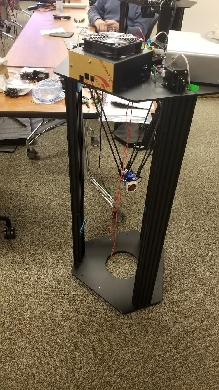
Finally received my tlm. And tasted to put it together
I'd upload a pic but I don't know how to resize it on my phone
-
heres the pics
-
ok im having some problems. i got the bord all wired up and it homes and dose the bed probe just fine. i used the reprap firmware setup tool to config the config.g im not sure i got the radius and such right though. all i know for sure is my arms are 400.21 and my printer radius is about 180mm not sure what the smart effector radius is. i think its about 3.5mm? i have the berdair pump set up on one of the pwm headers but it wont turn. it blips twice during start up. i use m106 to try to turn it on but nothing.
i tell the heat bed to go to 60 but i get no voltage out of the bed terminals. and the hot end dosent even try to turn on. im guessing its because i dont have a fan wired up for that yet. i think im going to have that as a always on fanhere is my config.g
0_1526517295903_config.g -
With regard to the various dimensions being right: Get the L parameter of the M665 correct (400.21), and then run a G32 to set everything else.
Be sure and save the G32 with an M500, and be sure your config.g contains an M501 to load the settings, somewhere near the end of config.g
-
I did have that parameter set correct. But it only probed a 210mm dai area of my 310mm bed. It said it was 10.something out before and 2.something out after.
-
@bendiesel said in tevo little monster duet wifi:
I did have that parameter set correct. But it only probed a 210mm dai area of my 310mm bed. It said it was 10.something out before and 2.something out after.
That's OK for now.
To fix that later, edit the bed.g file, and/or generate another one with the online configuration tool. The coordinates in that file determine where the probes occur.
Here is mine. I have a 604mm dia bed. So you could probably just half all of mine for a 300mm bed. Might be simpler in some ways that going all the way through the configurator for just one file.
; bed.g ; called to perform automatic delta calibration via G32 ; ; generated by RepRapFirmware Configuration Tool on Fri Apr 27 2018 13:01:19 GMT-0500 (Central Daylight Time) M561 ; clear any bed transform ; Probe the bed at 3 peripheral and 3 halfway points, and perform 6-factor auto compensation ; Before running this, you should have set up your Z-probe trigger height to suit your build, in the G31 command in config.g. G28 G30 P0 X0 Y275 H0 Z-99999 G30 P1 X238 Y-138 H0 Z-99999 G30 P2 X-238 Y-138 H0 Z-99999 G30 P3 X0 Y147 H0 Z-99999 G30 P4 X127 Y-73 H0 Z-99999 G30 P5 X-127 Y-73 H0 Z-99999 G30 P6 X0 Y0 H0 Z-99999 S6 ; Use S-1 for measurements only, without calculations. Use S4 for endstop heights and Z-height only. Use S6 for full 6 factors ; If your Z probe has significantly different trigger heights depending on XY position, adjust the H parameters in the G30 commands accordingly. The value of each H parameter should be (trigger height at that XY position) - (trigger height at centre of bed) -
@danal said in tevo little monster duet wifi:
@bendiesel said in tevo little monster duet wifi:
I did have that parameter set correct. But it only probed a 210mm dai area of my 310mm bed. It said it was 10.something out before and 2.something out after.
That's OK for now.
To fix that later, edit the bed.g file, and/or generate another one with the online configuration tool. The coordinates in that file determine where the probes occur.
Here is mine. I have a 604mm dia bed. So you could probably just half all of mine for a 300mm bed. Might be simpler in some ways that going all the way through the configurator for just one file.
; bed.g
; called to perform automatic delta calibration via G32
;
; generated by RepRapFirmware Configuration Tool on Fri Apr 27 2018 13:01:19 GMT-0500 (Central Daylight Time)
M561 ; clear any bed transform
; Probe the bed at 3 peripheral and 3 halfway points, and perform 6-factor auto compensation
; Before running this, you should have set up your Z-probe trigger height to suit your build, in the G31 command in config.g.
G28
G30 P0 X0    Y275  H0 Z-99999
G30 P1 X238  Y-138 H0 Z-99999
G30 P2 X-238 Y-138 H0 Z-99999
G30 P3 X0    Y147  H0 Z-99999
G30 P4 X127  Y-73  H0 Z-99999
G30 P5 X-127 Y-73  H0 Z-99999
G30 P6 X0    Y0    H0 Z-99999 S6
; Use S-1 for measurements only, without calculations. Use S4 for endstop heights and Z-height only. Use S6 for full 6 factors
; If your Z probe has significantly different trigger heights depending on XY position, adjust the H parameters in the G30 commands accordingly. The value of each H parameter should be (trigger height at that XY position) - (trigger height at centre of bed)
But you can also run DC42's Bed.G file generator
-
Thank you for the help. Now to figure out why it won't heat up
-
This post is deleted!