Beginner Needs Help - Anycubic Kossel Plus + Duet WiFi -- HOW?
-
Hi @dc42.
I believe these are 1.8 deg motors. But I apologize, I don't know what a tooth pulley is or where it's located on the printer.
Trying to google-fu the part, but not seeing it.
-
The pulleys I am referring to are on the stepper motor shafts. Each one will have 16 or 20 teeth on it - or just possibly 18.
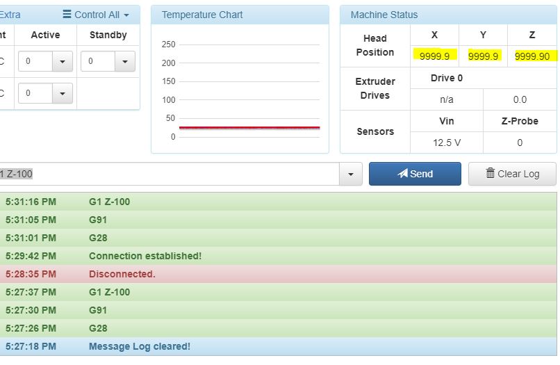
You can check that the steps/mm is correct. Home the printer, then send G91 followed by G1 Z-100. The effector should move down 100mm. If it moves some other distance, you have incorrect steps/mm set in config.g.
-
@mindbender9 in your first post, it shows your config.g contains
M92 X80 Y80 Z80 E663 ; Set steps per mmDouble check that this has not changed, because I believe this is probably correct.I have an Anycubic Kossel Linear (NOT plus) and it has 1.8 motors and 20 tooth pulleys, resulting in 80 steps per mm. 80 per mm works correctly in the Marlin/Trigorilla native printer (along with a 16 microstep setting).
As an aside, your steps/mm for your extruder look odd to me. My Anycubic is set to 96. Please note this is NOT your problem with movement/homing/probing... and you can check this later... just mentioning it because we are looking at M92.
As David said, be sure and home, then command a 100mm move and measure the results, just to be sure.
G28 G91 G1 Z-100 -
When I enter G28, the printer arms rise to the top and stop. G91 does nothing.
When I enter G1 Z-100, nothing happens and the arms remain in place at the top of the printer. No errors are registered in the G-code Console.
One interesting thing is the "Head Position" for all three axis are set at "9999.9" after homing. Would this be related?

Here's my config.g for reference:
; Configuration file for Duet WiFi (firmware version 1.20 or newer)
; executed by the firmware on start-up
;
; generated by RepRapFirmware Configuration Tool on Sun May 13 2018 19:16:40 GMT-1000 (Hawaiian Standard Time); General preferences
G90 ; Send absolute coordinates...
M83 ; ...but relative extruder moves
M555 P1 ; Set firmware compatibility to look like RepRapFirmare;*** The homed height is deliberately set too high in the following - you will adjust it during calibration.
M665 R134 L271 B85 H285 ; Set delta radius, diagonal rod length, printable radius and homed height
M666 X0 Y0 Z0 ; Put your endstop adjustments here, or let auto calibration find them; Network
M550 Pduettest
M552 S1 ; Enable network
M586 P0 S1 ; Enable HTTP
M586 P1 S0 ; Disable FTP
M586 P2 S0 ; Disable Telnet; Z-Probe
M558 P0 X0 Y0 Z1 H5 F1000 T5000 I1 ; Set Z probe type to MANUAL and the dive height + speeds
G31 X0 Y0 Z0 P100 ; Set Z probe trigger value, offset and trigger heightM557 R130 S20 ; Define mesh grid
; Drives
M569 P0 S1 ; Drive 0 goes forwards
M569 P1 S1 ; Drive 1 goes forwards
M569 P2 S1 ; Drive 2 goes forwards
M569 P3 S1 ; Drive 3 goes forwards
M350 X16 Y16 Z16 E16 I1 ; Configure microstepping with interpolation
M92 X80 Y80 Z80 E663 ; Set steps per mm
M566 X1200 Y1200 Z1200 E1200 ; Set maximum instantaneous speed changes (mm/min)
M203 X18000 Y18000 Z18000 E1200 ; Set maximum speeds (mm/min)
M201 X1000 Y1000 Z1000 E1000 ; Set accelerations (mm/s^2)
M906 X1000 Y1000 Z1000 E800 I30 ; Set motor currents (mA) and motor idle factor in per cent
M84 S30 ; Set idle timeout; Axis Limits
M208 Z0 S1 ; Set minimum Z; Endstops
M574 X2 Y2 Z2 S1 ; Set active high endstops; Heaters
M305 P0 T100000 B4267 C0 R4700 ; Set thermistor + ADC parameters for heater 0
M143 H0 S120 ; Set temperature limit for heater 0 to 120C
M305 P1 T100000 B4267 C0 R4700 ; Set thermistor + ADC parameters for heater 1
M143 H1 S275 ; Set temperature limit for heater 1 to 275C; Fans
M106 P0 S0.3 I0 F500 H-1 ; Set fan 0 value, PWM signal inversion and frequency. Thermostatic control is turned off
M106 P1 S1 I0 F500 H1 T45 ; Set fan 1 value, PWM signal inversion and frequency. Thermostatic control is turned on
M106 P2 S1 I0 F500 H1 T45 ; Set fan 2 value, PWM signal inversion and frequency. Thermostatic control is turned on; Tools
M563 P0 D0 H1 ; Define tool 0
G10 P0 X0 Y0 Z0 ; Set tool 0 axis offsets
G10 P0 R0 S0 ; Set initial tool 0 active and standby temperatures to 0C; Automatic saving after power loss is not enabled
M501
; Custom settings are not configured -
I have to ask: Is there a particular order or hierarchy for G-codes in the configuration files? Could that be a cause for the weird results/actions?
-
@mindbender9 said in Beginner Needs Help - Anycubic Kossel Plus + Duet WiFi -- HOW?:
One interesting thing is the "Head Position" for all three axis are set at "9999.9" after homing. Would this be related?
Yes! it means that the parameters in your M665 and M666 commands are mechanically impossible. What M665 and M665 commands do you currently have in config.g? Check that they are not being overridden by other commands in config-override.g.
-
Hi @dc42
My config.g has the following values for M665 and M666:
M665 R134 L271 B85 H285 M666 X0 Y0 Z0 My config-override.g file (which I had no idea existed) has the following values:
; This is a system-generated file - do not edit ; Delta parameters M665 L271.000 R134.000 H1032.754 B85.0 X0.000 Y0.000 Z0.000 M666 X250.573 Y79.532 Z-330.105 A0.00 B0.00 ; Heater model parameters M307 H0 A90.0 C700.0 D10.0 S1.00 V0.0 B1 M307 H1 A340.0 C140.0 D5.5 S1.00 V0.0 B0 M307 H2 A340.0 C140.0 D5.5 S1.00 V0.0 B0 M307 H3 A340.0 C140.0 D5.5 S1.00 V0.0 B0 M307 H4 A340.0 C140.0 D5.5 S1.00 V0.0 B0 M307 H5 A340.0 C140.0 D5.5 S1.00 V0.0 B0 M307 H6 A340.0 C140.0 D5.5 S1.00 V0.0 B0 M307 H7 A340.0 C140.0 D5.5 S1.00 V0.0 B0 I’m guessing that those wild numbers in the config-override.g file should not be there? Should their M665 and M666 values match the config.g G-code values?
-
The values in config-override.g were written when you ran M500 after auto calibrating. I suggest you delete them and restart the Duet. When you have auto calibration working well and you no longer have those 9999.9 values for the axis positions, you can run M500 to save the new values to config-override.g.
It is the M666 values in config-override.g that are causing the problem.
-
With your advice, I did a manual 6 point calibration using the paper test. I'm now able to do a test print of a 1-layer circle, but it's really ragged and rough. It's not pretty, but it's my first print and I'm psyched!

I'll have to figure out how to clean this up and fine-tune it a little more before printing the IR sensor bracket (my first real 3D printing project).
With all honesty, you and the forum contributors made it possible for me to get this far. Thank you very much for this breakthrough, David/@dc42.
This is a great start, and I appreciate everyone's help!
-
Hi, pardon me for butting in, so-to-speak, I have an AnyPubic which I bought via Amazon. It was advertised as being a "Kossel Linear Plus" model, but it turns out that it was likely not, as, it did not include a heat bed, the rod arms were different length from later 'plus' models, there was no Z-probe, no software, no configuration settings and the advertised u-tube tutorials for my model printer had been pulled down by an engineer at AnyCubic headquarters in China, "be back soon", but it was not uploaded within a year span. Finally after screwing around for many months with no info, sloppy rod-end bearings (Heim joints), and a TriGorilla board (no schematics or parts list) which caught fire, I wrote the factory (I have the e-letter if anyone cares to read it), and asked them for technical help with that printer sold by their vendor. Their answer was, "buy our new printer, only $250, it solves all the problems of the other printer". Hah hah hah. I'd like to wring their necks. All kidding aside...
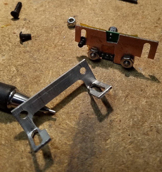
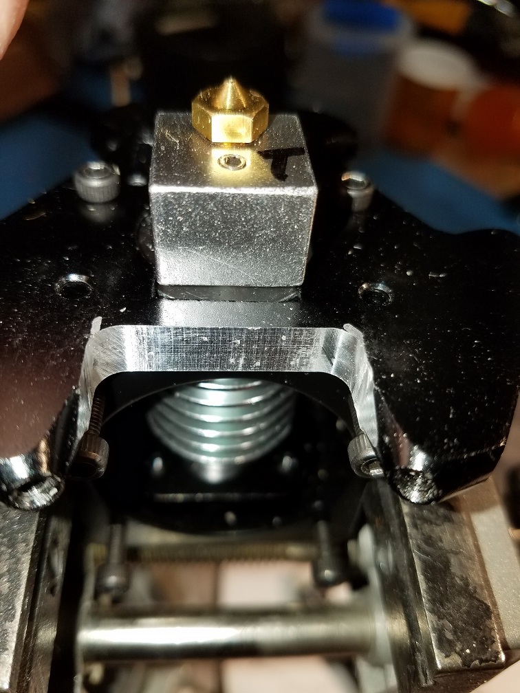
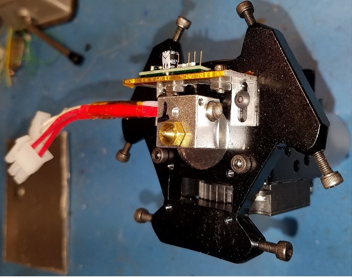
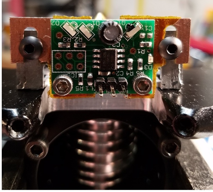
Re; the DUET Mini-IR Z-Probe. If the AnyCubic effector (the plate that holds the print-nozzle) has not been physically changed from the version AC sold me, you will likely have to make a mounting adapter. I used a mini-mill to machine a cutout on the aluminum effector plate and also hacked & milled an aluminum 12mm/(half inch) right-angle bracket profile and then used a scrap peice of 1,60mm/0.062" PCB copper board as a heat shield. It mounted perfectly and was adjustable. I'm including a few photos for you to review so that you may make your own adapter or have some ideas. I'm now using the IR sensor in a different non-printer gadget. It works beautifully in the other gadget.
It is my opinion that you will be a happy camper should you elect to acquire the DC42 'Smart-Effector', with the Haydan rods+mag-joints and in-built Z-Sensor, and for a few more bucks, get an authentic E3D V6 HotEnd for that effector. That marriage makes for an excellent solution in my opinion. Everything DC42 (and many of the elmers here) say is golden. And I agree, that the wiki does read like an engineer's notes. 3D Printers are in their infancy, --everything mainly is experimental. The technical evolution of this art is roughly about the same as it was for hobbyiest personal-computers (before IBM trade-marked the 'name') in the US, around 1975.
Good luck...
3mm
LA, Ca, USa
-
Hi @3mm ,
I'd like to thank you for your suggestions re: the Anycubic Kossel printer and for sharing your 3D printing experiences as well. If only I read this 1.5 months prior....
FWIW, my experiences with both Anycubic3d and the reseller have been poor overall. And the issues that you've run into are very similar to mine - I'm looking at all of this as a learning experience and hope to be able to laugh this off once I get my prints running well.
BTW, that smart effector and hot-end look great - did you drill and place the hot-end through the center circle on the smart effector? I've read great things about the smart effector, but will have to upgrade my control arms to carbon fibre and mag-balls first (as @Danal recommended).
Thanks again for your tips for upgrading. Best regards!
-
The photos I uploaded are not of the Smart-Effector, but rather are the DC42 Mini-IR Z-Height Sensor and adapter I made, which I originally used, but which I discovered that because I did not have the 'standard' AnyCubic heat-bed, but rather an after-market bed that I bought on eBay, which is highly reflective, the IR Z-Probe doesn't work well with my heat-bed. So, after much research and reading folks experiences with the Smart-Effector, I acquired it, and it works perfectly. The Smart-Effector has a bunch of engineering 'wins' in my opinion, everything is on connectors, enabling easy universal swap-outs, or parts replacement/repairs. It is a slick design and unlike a lot of stuff out there it is very reasonably priced too. And frankly, the tech support provided by DC42 is also excellent, and is one of the reasons I bought the Escher products. This stuff is tricky and complicated. I tip my hat to those folks out there who were able to get their AnyCubic printers to work without any tech-support...or...maybe I'm stupid?
Take a long look at the Smart-Effector, you won't be disappointed.
3mm
-
While there are various vendors that supply the rod-arms, one of the vendors that I buy from, UltiBots has the Hayden 'MagBall-Arms', 288mm length with Delrin mag-ends. The Delrin mag-ends don't wear as quickly as the 3D printed mag-ends do.
This vendor also supplies metal vertex corners, acquired via advice here on DUET3D board that was suggested. There is a minor gotcha with those corners, but there is a kiwi workaround for the problem, which so far is working out ok.
Also, I've also had to do a bit of kiwi eng'g with the AnyCubic top-of-tower end-stop micro-switches. At some future juncture I will design and print an adjustable micro-switch mount adapter to properly resolve the matter or perhaps, replace the switches with optical-interrupter sensors? When I wired the towers, I wired them using 3 wire SpectrStrip ribbon cable with an eye for future optical sensor installation. The problem is that the top-of-tower end-stop 'adjustment' screw is misaligned with the micro-switch lever. I cutup an old credit-card, glued it to the lever using Goop (great glue) to widen the lever. This is working well.
Later today I'll upload a couple photos for you to see what I'm describing. The YL is encouraging me to run a few errands.
3mm
-
@3mm said in Beginner Needs Help - Anycubic Kossel Plus + Duet WiFi -- HOW?:
While there are various vendors that supply the rod-arms, one of the vendors that I buy from, UltiBots has the Hayden 'MagBall-Arms', 288mm length with Delrin mag-ends. The Delrin mag-ends don't wear as quickly as the 3D printed mag-ends do.
Yes, this is the biggest single upgrade for this printer.
-
Ok. I'm still having problems.
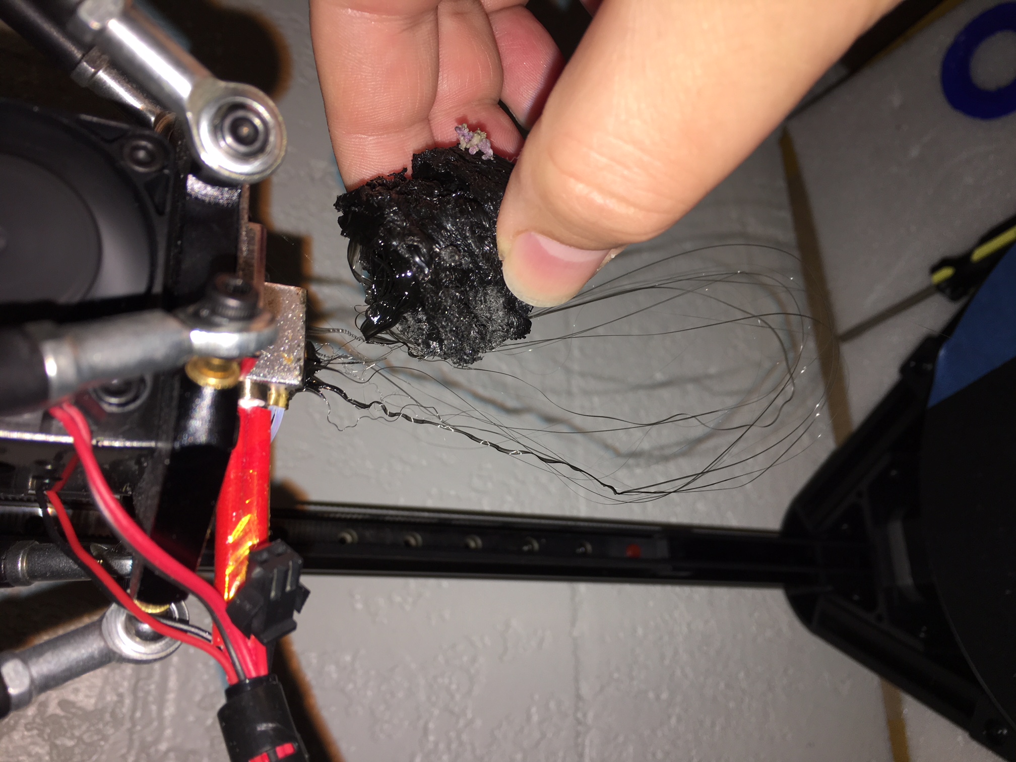
- While it prints something, the results are generally terrible. Take a look at these results:


- Auto-calibrating the delta manually at 13 points still doesn't correctly set the nozzle to the bed. I've realized that my bed is lower (height-wise) on one side than the other two sides. Yet the printer nozzle can't adjust to this height difference and dumps filament 2-3cm off the surface on one end. On another end, the nozzle scrapes along the bed surface like Z=-something.
Here are my bed.g and homedelta.g files. How can we fix this?
; bed.g
; called to perform automatic delta calibration via G32 ; ; generated by RepRapFirmware Configuration Tool on Sun May 13 2018 19:16:40 M561 ; clear any bed transform G31 X0 Y0 ; don't want any probe offset for this - ADDED 5/21/2018 G28 ; home the printer M401 ; deploy the Z probe ; 13 points, 7 factors, probing radius: 85, probe offset (0, 0) G30 P0 X0.00 Y85.00 Z-99999 H0 G30 P1 X73.61 Y42.50 Z-99999 H0 G30 P2 X73.61 Y-42.50 Z-99999 H0 G30 P3 X0.00 Y-85.00 Z-99999 H0 G30 P4 X-73.61 Y-42.50 Z-99999 H0 G30 P5 X-73.61 Y42.50 Z-99999 H0 G30 P6 X0.00 Y42.50 Z-99999 H0 G30 P7 X36.81 Y21.25 Z-99999 H0 G30 P8 X36.81 Y-21.25 Z-99999 H0 G30 P9 X0.00 Y-42.50 Z-99999 H0 G30 P10 X-36.81 Y-21.25 Z-99999 H0 G30 P11 X-36.81 Y21.25 Z-99999 H0 G30 P12 X0 Y0 Z-99999 S7 M402 ; retract the Z probe G1 X0 Y0 Z150 F15000 ; get the head out of the way of the bed ; homedelta.g
;
; generated by RepRapFirmware Configuration Tool on Sun May 13 2018 19:16:40
G91                        ; relative positioning
G1 S1 X282 Y282 Z282 F1800 ; move all towers to the high end stopping at the endstops (first pass)
G1 X-5 Y-5 Z-5 F1800 S2    ; go down a few mm
G1 S1 X10 Y10 Z10 F360     ; move all towers up once more (second pass)
G1 Z-5 F6000               ; move down a few mm so that the nozzle can be centred
G90                        ; absolute positioning
;G1 X0 Y0 F6000            ; move X+Y to the centre
I'm lost. Again.
-
@danal said in Beginner Needs Help - Anycubic Kossel Plus + Duet WiFi -- HOW?:
As an aside, your steps/mm for your extruder look odd to me. My Anycubic is set to 96. Please note this is NOT your problem with movement/homing/probing... and you can check this later... just mentioning it because we are looking at M92.
What is the G-code that has the wrong value, and what should a correct value be for a stock extruder? Thanks.
-
@mindbender9 said in Beginner Needs Help - Anycubic Kossel Plus + Duet WiFi -- HOW?:
I'm lost. Again.
Please post your MOST RECENT config.g and config_override.g. If you've delete config_override.g, that is OK, just clearly state that.
.
G32 runs bed.g and yours looks OK (but not great, see a couple of posts below) for an Anycubic kossel plus. The G32/bed.g process sets Z-Height, Delta-Radius, and X,Y, and Z correction factors. It does NOT set rod length or Bed size, you have to set those prior to the G32. In the M665 below, the things that YOU set are italicized., the things that G32 sets are bolded
I'm about 99% confident the italicized values below are correct for your printer.
M665 L222 R123.45 H123.45 B115 X-0.047 Y0.425 Z0.000
G32 is also NOT bed leveling. If your bed is a full 2mm off level, you need to get it mechanically closer, and/or adjust the screws that touch the endstops (at the top). Adjust one single screw a little, home (G28), move the nozzle close to the bed (G0 Z0), then move the nozzle across the bed (G0 X0 Y110, or G0 X0 Y-110, or G0 Y0 X110 or G0 Y0 X-110). Repeat, very slowly and patiently. This will take a while.
Eventually, we'll get to mesh bed leveling... nonetheless, it should be mechanically closer than 2mm.
-
@mindbender9 said in Beginner Needs Help - Anycubic Kossel Plus + Duet WiFi -- HOW?:
@danal said in Beginner Needs Help - Anycubic Kossel Plus + Duet WiFi -- HOW?:
As an aside, your steps/mm for your extruder look odd to me. My Anycubic is set to 96. Please note this is NOT your problem with movement/homing/probing... and you can check this later... just mentioning it because we are looking at M92.
What is the G-code that has the wrong value, and what should a correct value be for a stock extruder? Thanks.
M92 X80 Y80 Z80 E663 ; Set steps per mm
That setting should probably be E96. Unless Anycubic has changed to a different extruder or something.
.
To verify correct setting (and I'd try E96 first):
-
Remove filament from the hot end (i.e. heat it up and pull it out)
-
Remove the bowden tube below the extruder motor. (press the collet up and pull the tube down)
-
Load some filament into the extruder motor so that it just hangs out the bottom (because you removed the bottom tube in step (2)).
-
Mark the filament, with a marker or a piece of tape, EXACTLY at the bottom of the extruder. Don't let the collet fool you, it moves a mm or so... measure consistently.
-
Extrude 100mm of filament. Either with a control panel, or the web interface.
-
Measure, carefully, from the bottom of the extruder to your mark. Should be EXACTLY 100mm.
You can extrude and retract a couple of times, and measure, if you want to really verify.
Report back here if it is NOT 100mm measurement.
-
-
Your bed.g looks like it was generated at http://www.escher3d.com/pages/wizards/wizardbed.php with inputs:
Number of peripheral points: 6 Number of halfway points: 6 Number of calibration factors: 7 Probing radius: 85 Probe offset from nozzle: X: 0.0 Y: 0.0 Options: Home towers at start Deploy/retract probe Or similar. This is OK-ish. It is a little small on radius and has a lot of points for a manual calibration. Were I doing manual calibration, I'd use these parameters:
Number of peripheral points: 3 Number of halfway points: 3 Number of calibration factors: 6 Probing radius: 105 Probe offset from nozzle: X: 0.0 Y: 0.0 Options: Home towers at start Deploy/retract probe Resulting in this file:
; bed.g file for RepRapFirmware, generated by Escher3D calculator ; 10 points, 6 factors, probing radius: 105, probe offset (0, 0) G28 M98 Pdeployprobe.g G30 P0 X0.00 Y105.00 Z-99999 H0 G30 P1 X90.93 Y52.50 Z-99999 H0 G30 P2 X90.93 Y-52.50 Z-99999 H0 G30 P3 X0.00 Y-105.00 Z-99999 H0 G30 P4 X-90.93 Y-52.50 Z-99999 H0 G30 P5 X-90.93 Y52.50 Z-99999 H0 G30 P6 X0.00 Y52.50 Z-99999 H0 G30 P7 X45.47 Y-26.25 Z-99999 H0 G30 P8 X-45.47 Y-26.25 Z-99999 H0 G30 P9 X0 Y0 Z-99999 S6 M98 Pretractprobe.g That should give you better results with less manual work.
-
; config-override.g - After running your instructions above a couple of times.
; Delta parameters
M665 L269.146 R263.947 H386.312 B85.0 X45.291 Y16.851 Z0.000
M666 X7.276 Y22.820 Z-30.096 A0.00 B0.00
; Heater model parameters
M307 H0 A90.0 C700.0 D10.0 S1.00 V0.0 B1
M307 H1 A340.0 C140.0 D5.5 S1.00 V0.0 B0
M307 H2 A340.0 C140.0 D5.5 S1.00 V0.0 B0
M307 H3 A340.0 C140.0 D5.5 S1.00 V0.0 B0
M307 H4 A340.0 C140.0 D5.5 S1.00 V0.0 B0
M307 H5 A340.0 C140.0 D5.5 S1.00 V0.0 B0
M307 H6 A340.0 C140.0 D5.5 S1.00 V0.0 B0
M307 H7 A340.0 C140.0 D5.5 S1.00 V0.0 B0
; config.g
; Configuration file for Duet WiFi (firmware version 1.20 or newer) ; executed by the firmware on start-up ; ; generated by RepRapFirmware Configuration Tool on Sun May 13 2018 19:16:40 ; General preferences G90 ; Send absolute coordinates... M83 ; ...but relative extruder moves M555 P1 ; Set firmware compatibility to look like RepRapFirmare ;*** The homed height is deliberately set too high in the following - you will adjust it during calibration. M665 R134 L271 B85 H285 ; Set delta radius, diagonal rod length, printable radius and homed height M666 X0 Y0 Z0 ; Put your endstop adjustments here, or let auto calibration find them ; Network M550 Pduettest M552 S1 ; Enable network M586 P0 S1 ; Enable HTTP M586 P1 S0 ; Disable FTP M586 P2 S0 ; Disable Telnet ; Z-Probe M558 P0 X0 Y0 Z1 H5 F1000 T5000 ;I1 ; Set Z probe type to MANUAL and the dive height + speeds G31 X0 Y0 Z0 P100 ; Set Z probe trigger value, offset and trigger height M557 R130 S20 ; Define mesh grid ; Drives M569 P0 S1 ; Drive 0 goes forwards M569 P1 S1 ; Drive 1 goes forwards M569 P2 S1 ; Drive 2 goes forwards M569 P3 S1 ; Drive 3 goes forwards M350 X16 Y16 Z16 E16 I1 ; Configure microstepping with interpolation M92 X80 Y80 Z80 E96 ; Set steps per mm M566 X1200 Y1200 Z1200 E1200 ; Set maximum instantaneous speed changes (mm/min) M203 X18000 Y18000 Z18000 E1200 ; Set maximum speeds (mm/min) M201 X1000 Y1000 Z1000 E1000 ; Set accelerations (mm/s^2) M906 X1000 Y1000 Z1000 E800 I30 ; Set motor currents (mA) and motor idle factor in per cent M84 S30 ; Set idle timeout ; Axis Limits M208 Z0 S1 ; Set minimum Z ; Endstops M574 X2 Y2 Z2 S1 ; Set active high endstops ; Heaters M305 P0 T100000 B4267 C0 R4700 ; Set thermistor + ADC parameters for heater 0 M143 H0 S120 ; Set temperature limit for heater 0 to 120C M305 P1 T100000 B4267 C0 R4700 ; Set thermistor + ADC parameters for heater 1 M143 H1 S275 ; Set temperature limit for heater 1 to 275C ; Fans M106 P0 S0.3 I0 F500 H-1 ; Set fan 0 value, PWM signal inversion and frequency. Thermostatic control is turned off M106 P1 S1 I0 F500 H1 T45 ; Set fan 1 value, PWM signal inversion and frequency. Thermostatic control is turned on M106 P2 S1 I0 F500 H1 T45 ; Set fan 2 value, PWM signal inversion and frequency. Thermostatic control is turned on ; Tools M563 P0 D0 H1 ; Define tool 0 G10 P0 X0 Y0 Z0 ; Set tool 0 axis offsets G10 P0 R0 S0 ; Set initial tool 0 active and standby temperatures to 0C ; Automatic saving after power loss is not enabled M501 ; Custom settings are not configured