Dual Z Wiring Again
-
From studying the Duet3d Ethernet i have ordered i understand the board has two rows of connectors that can be used to control two Z motors and they behave identical.
My questions is what if you use the Duet Expansion Breakout Board which i will have to do after testing in the lab due to fact the machine we are retrofitting has very large Nema 34 motors and already has Automation Direct STP-DRV-6575 Drives and management says to use them. I have a little understanding when it gets to that point that you have to remap the drives etc. but how would you wire the board so that two Z axis motors would behave exactly the same. The carriage on this machine is very larger, about 60 by 60 inches and has two stepper motors on each side to control the Z movement.
Could you parallel the wiring that you would use for E4 on the Breakout board that will be wired into one of the external Stepper Drives to the second Stepper Drive?
Thanks -
This post is deleted! -
If you want two stepper motors to be connected to external drivers in the same manner as the z connectors on the duet's internal driver, you should connect them in series to one single driver output.
-
Bot
Thanks, could you explain in a little more detail. The wires coming of the Step, Direction etc. from E4 on the breakout board would go to the external stepper controller #1, how would you connect to stepper controller #2 -
You only connect one set of inputs from the breakout board to the external stepper. Then, from that external stepper driver, you will wire two stepper motors in series. You will only need one stepper driver to control two motors, if you want them to behave the same way as the Z connector on the duet.
Bear in mind, the drivers themselves will be different than the internal ones, so they won't behave the same... but the connection will be the same.
-
If it's the series or parallel wiring that you don't understand, this is going to be difficult for you to do well.
As stated, you only use one driver. For parallel wiring, each motor will only get half of the current, but see full voltage that goes through your driver. For series wiring, each motor will get the full current, but see half of the voltage. The drivers limit voltage in order to regulate current, so this is okay, so long as your driver has enough voltage going to it to have spare.
RAMPS boards, are typically used with 12V, and so they wire two Z motors in parallel, in order to maximize the avaialable voltage. The Duet by default operates those motors in series, as it is better designed to take advantage of 24V power input, though it can also operate at 12V.
The outputs from your stepper driver determine which it is. Call the motors Z1 and Z2. each of these has 2 coils, A and B, each coil has 2 terminals, 1 and 2.
Your stepper driver has 4 outputs, A2(out) A1(out) B1(out) B2(out) named for the coils and terminals.
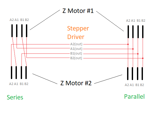
In parallel wiring:
A2(out) goes to both Z1A2 and Z2A2
A1(out) goes to both Z1A1 and Z2A1
B1(out) goes to both Z1B1 and Z2B1
B2(out) goes to both Z1B2 and Z2B2In this way, whatever the driver puts out gets split between both motors
In series wiring:
A2(out) goes to Z1A2
Z1A1 goes to Z2A2
Z2A1 goes to A1(out)
B1(out) goes to Z1B1
Z1B2 goes to Z2B1
Z1B2 goes to B2(out)If there is no motor connected to the Z2 connector, then you must jumper Z2A2/Z2A1 and Z2B1/Z2B2 or else the whole thing becomes an open circuit and the other motor will not turn at all. (You will get the exact same situation by swapping the jumpers to the Z1 connector and the motor to the Z2 connector.)
I was going to do up a diagram, but I'm not sure that what I could do quickly would be any clearer.
It is also possible to use multiple stepper drivers with each connected to an individual Z motor, but in this case, you would use a different step/direction channel. Unless you are looking to run stepper motors that require more power, and a single driver cannot handle more than one motor's voltage/current needs, in which case, you might want to reconsider component selection. The duet firmware can deal with multiple motors for any given axis.
-
Thanks, will read in more detail but it appears your description, which is a great write up is explaining how to wire the output side of the stepper drive to two motors. What i was wondering is, is there a way to wire from the A4 terminal of the breakout board Step+, Step -, etc. to the input of both external stepper driver controllers? Or like on the main Duet board there are two connectors labeled Z and one has a jumper that if i understand correctly you remove to add another Z motor and both Z motors are then controlled identical through the connections of the main Duet board. Hope i can explain without being too confusing.
Thanks -
The Duet's 2 Z motor ports are wired in series to a single driver, which is why they have the jumpers on the second connector.
It may be possible to wire multiple drivers to a single step/dir output, however I don't think that there is much advantage to this. It would be better to choose the stepper drivers that are capable of driving the intended load.
-
Easiest IMO would be to wire the 2 external drivers to separate outputs on the expansion breakout board, and use the M584 command to map Z to both of them.
-
Thanks to everyone. I realized on the drive home after getting off work that i was wrong in my previous post.
Spoke before i fully thought. As soon as i got in the car i realized that dummy, the two connectors on the board as SupraGuy said are wired in series to a single driver and then realized as DC42 said, just remap both to be a Z, which is why i chose the Duet over others in first place. Not that great with the G code but hope to get a lot better .
Thanks to everyone, learned to read and think about it a little longer before rushing to ask.
Have a great weekend.