Filament Runout switch on Duet 0.6
-
It's harmless to try without. The risk is that it might sense the switch as closed when it is open.
-
Thanks DC.
I am sorry to keep pushing questions... I have the switch attached and was wondering how to check the status of this switch. I would think M119 would report that (like the XYZ endstops and the Z-probe status) but it doensn't. Also I see some posts mentioning a status in DWC but I don't see any position where to find that (presumably at the sensor grid in the upper right of DWC window).Whether filament is in or out the switch DWC is telling me the filament is out immediatly when T1 wants to start heating.
I have put:
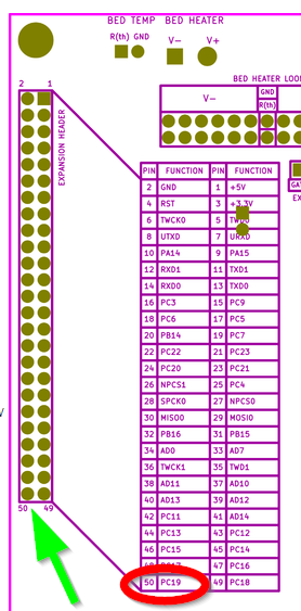
M591 D0 P2 C7 S1
in the config.gAs I understand it C7 stands for Endstop E4, and that is pin50 on the expansion slot.
I have the other side of the switch connected to GND Pin 2
When connected to to +3.3V Pin 3 nothing happens at all so I guess I should connect it to ground indeed, but I am uncertain.I checked the switch, and it works normally. I get 0 Ohms when I pull the filament out, so I guess I should use P2 indeed.
So, what am I doing wrong?
-
@dc42 said in Filament Runout switch on Duet 0.6:
You may also need to connect a pullup resistor between that endstop connection on the expansion connector and the +3.3V pin.
I read somewhere that for most 3.3V applications a 10K resistor will do. Should I simply use something like this?
https://www.conrad.nl/p/koolfilmweerstand-10-k-axiaal-bedraad-0207-025-w-5-yageo-cfr-25jt-52-10k-1-stuks-1417697 -
@deltacon said in Filament Runout switch on Duet 0.6:
@dc42 said in Filament Runout switch on Duet 0.6:
You may also need to connect a pullup resistor between that endstop connection on the expansion connector and the +3.3V pin.
I read somewhere that for most 3.3V applications a 10K resistor will do. Should I simply use something like this?
https://www.conrad.nl/p/koolfilmweerstand-10-k-axiaal-bedraad-0207-025-w-5-yageo-cfr-25jt-52-10k-1-stuks-1417697Yes.
-
I am not getting it to work... Does the switch go between Endstop pin and GND or between Endstop pin and +3.3V?
I have put a resistor 10K Ohm between Endstop pin and +3.3V like David suggested.
M591 D0 P1 C7 S1 is in my config.g, C7 since I am connecting to extruder endstop 4If I connect to GND the Duet becomes unresponsive until disconnection.
If I connect it to +3.3V nothing happensWith switch on +3.3V I measure
- With filament present 0.001V and 8.7K Ohm
- With filament absent 0.000V and 0.0K Ohm
The +3.3V pin gives 3.3V correctly, measured against GND
I also tried the external trigger M581 E7 T1 S0 C1 command (tried E4 also, because I was unsure if there also the axes endstops are counted). But no change whatsoever.
Any ideas?
-
Are you sure that you have connected it to the correct endstop input pin on the expansion connector? With the resistor connected between that pin and +3.3V, the voltage on the pin relative to ground should be 0V when the switch is closed and almost 3.3V when the switch is open.
Duet WiFi hardware designer and firmware engineer
Please do not ask me for Duet support via PM or email, use the forum
http://www.escher3d.com, https://miscsolutions.wordpress.com -
@dc42 Yes I think so. I wanted to use the endstop pin for E4:

And on thye board that is the far left pin closest to the edge of the board:

Do I need to "activate this endstop by a "M574 E4 S1" command in config.g?
-
Okay, I had a little success!
I rewired today because I wanted to remeasure David's suggestion above. And now it seems to work as intended! Excellent! No Idea what I did wrong the first try. Thanks David for your assistence! -
I am running this filament runout setup in test mode now. It is functional, but the filament is not running through the switch for now. Pulling a small piece of filament out of the switch makes a pause happening just fine. However during normal prints, with a piece of filament present in the switch, it happens every now and then that a false positive (negative?) is triggered. I am confident that it is not the switch itself causing the problem. What else can make a trigger happen? EMI? Is the pullup resistor 10K Ohms no. Should I increase or lower the resistor?
-
If it's a normal 3-terminal microswitch then I suggest you use the 2 contacts that are closed when filament is present and open when it is not. That will make the wiring less sensitive to noise pickup than the other way round.
-
Yeah, that makes sense even for an electronics noob like me
")
I changed that, and will report back. Thanks!