Triggers on duex2
-
Hey all,
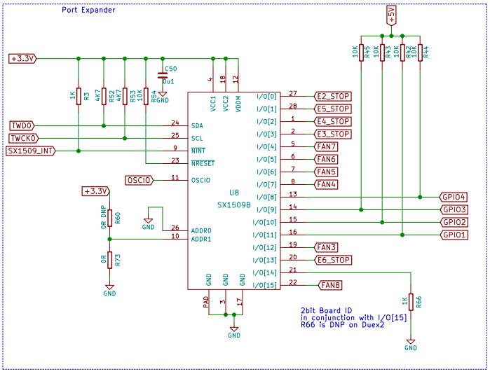
I'am working on 3d printer powered by duet Ethernet + duex2 combo and I have trouble with getting triggers on E4 E5 E6 to work. Situation is weird because E3 E2 works completely fine and they are also on expansion board and signals goes thru the same IC. I have checked ribbon cable, it's not damaged.
That makes me think fault is on my side. Did any of you have a similar issue? Any idea how to solve that?
my config file:; Configuration file for Duet WiFi (firmware version 1.21)
; executed by the firmware on start-up
;
; generated by RepRapFirmware Configuration Tool v2 on Fri Jan 11 2019 12:58:25 GMT+0100 (czas środkowoeuropejski standardowy); General preferences
G90 ; Send absolute coordinates...
M83 ; ...but relative extruder moves
;M564 S0 H0 ; Unlock movment; Network
M552
M550 P"Gamgolbot" ; Set machine name
M552 P192.168.0.123 S1 ; Enable network and acquire dynamic address via DHCP
M586 P0 S1 ; Enable HTTP
M586 P1 S0 ; Disable FTP
M586 P2 S0 ; Disable Telnet; Drives
M569 P0 S1 ; Drive 0 goes forwards
M569 P1 S1 ; Drive 1 goes forwards
M569 P2 S1 R1 ; Drive 2 goes forwards
M569 P3 S1 ; Drive 3 goes forwards S1 R1
M569 P4 S0 ; Drive 4 goes forwards S1 R1
M569 P5 S0 ; Drive 5 goes forwards
M584 X7 Y8 Z9 E3:4:0 ; Apply custom drive mapping
M350 X1 Y1 Z1 I0 ; Configure microstepping without interpolation
M350 E16:16:16 I1 ; Configure microstepping with interpolation
M92 X258.5 Y258.5 Z1600 E420:420:420 ; Set steps per mm
M566 X900.00 Y900.00 Z12.00 E120.00 ; Set maximum instantaneous speed changes (mm/min)
M203 X6000.00 Y6000.00 Z180.00 E1200.00 ; Set maximum speeds (mm/min)
M201 X500.00 Y500.00 Z20.00 E250.00 ; Set accelerations (mm/s^2)
M906 X800.00 Y800.00 Z800.00 E1300.00 I30 ; Set motor currents (mA) and motor idle factor in per cent
M84 S30 ; Set idle timeout; Axis Limits
M208 X-86.363 Y0 Z0 S1 ; Set axis minima 10+ 86.363
M208 X934 Y1060 Z1200 S0 ; Set axis maxima 980-86.363 1050-10 M208 X925 Y1040 Z1200 S0; Endstops
M574 X1 Y2 S1 ; Set active low endstops, x_min y_max
;filament sensors; Inputs
M581 T4 S1 Z ; emergency trigger
M581 T3 S1 E3 ; open door trigger
M581 T2 S1 E2 ; Fuses trigger; Outputs
M307 H0 A-1 C-1 D-1 ; disable heater 0 to make available output
M106 P3 I-1 ; disable fan 3 to make available output
M42 P23 S0 ; turn off power for steppers and bed heaters; servo output
M307 H7 A-1 C-1 D-1 ; Disable E7 heater to make available output
M280 P7 S86 I1 ; Remap H7 to servo, invert signal I1
M280 P7 S86
M400; Z-Probe
M574 Z1 S2 ; Set endstops controlled by probe
M558 P1 I0 H2 F120 T6000 A20 S0.02 ; Set Z probe type to modulated and the dive height + speeds
G31 P300 X43.1815 Y29 Z0 ; Set Z probe trigger value, offset and trigger height
M557 X-43.1815:977.1815 Y0:1089 S113.35:121 ; Define mesh grid M557; Heaters
M140 P0 H3 ; heated bed A
M140 P1 H4 ; heated bed B
M140 P2 H5 ; heated bed CM305 P3 X203 S"A" ; Configure thermocouple for heater bed 1
M143 H3 S100 ; Set temperature limit for heater 1 to 100C
M307 H3 F5 A52.3 C109.4 D3.1 S1.00 V24.1 B0M305 P4 X201 S"B" ; Configure thermocouple for heater bed 2
M143 H4 S100 ; Set temperature limit for heater 2 to 100C
M307 H4 F5 A62.0 C294.2 D5.0 S1.00 V24.1 B0M305 P5 X202 S"C" ; Configure thermocouple for heater bed 3
M143 H5 S100 ; Set temperature limit for heater bed 3 to 100C
M307 H5 F5 A34.7 C65.1 D3.6 S1.00 V24.1 B0M305 P1 T100000 B4138 R4700 X1 ; Set thermistor + ADC parameters for nozzle heater and remap it to channel 1
M143 H1 S280 ; Set temperature limit for heater 4 to 280CM305 P2 T100000 B4138 R4700 X2 ; Set thermistor + ADC parameters for nozzle heater and remap it to channel 2
M143 H2 S280 ; Set temperature limit for heater 5 to 280C;M305 P6 T100000 B4138 R4700 X5 ; Set thermistor + ADC parameters for heater 5 and remap it to channel 2
;M143 H6 S50 ; Set temperature limit for heater 5 to 50C; Fans
M106 P0 S0 I0 F100 L0 X122 H-1 C"lewy" B0.1 ; Set fan 0 value, PWM signal inversion and frequency. Thermostatic control is turned off
M106 P1 S0 I0 F100 L0 X122 H-1 C"prawy" B0.1 ; Set fan 1 value, PWM signal inversion and frequency. Thermostatic control is turned off
;M106 P3 S0 I0 F100 L0 H-1 C"chlodzenie wody" B0.1 ; Set fan 1 value, PWM signal inversion and frequency. Thermostatic control is turned off; Tools
M563 P1 S"glowica lewa" D0:2 H1 F0 ; Define tool 1
G10 P1 X0 Y0 Z0 ; Set tool 1 axis offsets
G10 P1 R0 S0 ; Set initial tool 1 active and standby temperatures to 0C
M563 P2 S"glowica praw" D1 H2 F1 ; Define tool 2
G10 P2 X86.363 Y0 Z0 ; Set tool 2 axis offsets
G10 P2 R0 S0 ; Set initial tool 2 active and standby temperatures to 0C
M563 P3 S"STOL" H3:4:5 ; Define tool 3
G10 P3 X0 Y0 Z0 ; Set tool 2 axis offsets
G10 P3 R0 S0 ; Set initial tool 2 active and standby temperatures to 0C
;M563 P6 S"chlodzenie wodne" H6 F3 ; Define tool 3; Automatic power saving
M911 S20 R22 P"M913 X0 Y0 G91 M83 G1 Z3 E-5 F1000" ; Set voltage thresholds and actions to run on power loss; Custom settings are not configured
; Miscellaneous
;M501 ; Load saved parameters from non-volatile memoryT1 ; Select first tool
G4 S5 ; wait 5s
M42 P23 S1 ; then turn on power for steppers and bed heaters
M400
M582 T4 -
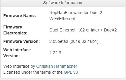
Which firmware version?
Do the endstop states show correctly in the Machine Properties page of DWC?
-
It doesn't show more than E2. LEDs next to E4 E5 E6 are working as they should.

-
Unless I'm being thick, I don't see anything in your config.g to configure E4 , 5 and 6 to work as external triggers.
You've got this:
M581 T4 S1 Z ; emergency trigger
M581 T3 S1 E3 ; open door trigger
M581 T2 S1 E2 ; Fuses triggerand I'd have thought you also need M581 Tn Sn E4 (5 and 6)
-
It looks to me that DWC Machine properties only shows as many endstop as drives it knows about. So check your M584 command and add extruders if necessary. For example, if M584 without parameters reports E3:4:5 then send M84 E3:4:5:6:7:8:9. Then create a tool using extruder 6 (aka drive 9) e.g. M563 P10 D9. After that, Machine Properties should report all the endstop states (it worked for me).
