ST-M5045 Driver wiring
-
Anyone have any luck wiring ST-M5045 to the Duet2 wifi? I had these wired on a smoothie board and even a MKS Base board just fine. For some reason they will no work on the Duet. I purchased a expansion board but believe it may not work? ( Not entirely sure what the chip does but its double soldered on 2 separate areas. So I have tried to wire it straight off the pin outs and still no luck (the motors wont even lock when power is up) I have checked En (-) and En (+) and get 3v. I have also sent a travel command and checked Dir (+) and get 3v when the software is pushing the signal. Attached is the board and how I have it wired.

-
Without the expansion board:
- Connect the 3 negative inputs of your drivers to ground on the Duet
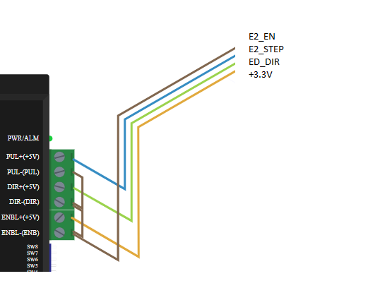
- Connect the PUL+, Dir+ and EN+ inputs to E2_STEP, E2_DIR ande E2_EN on the Duet
- Invert the enable signal using the R1 parameter of the M569 command for that driver in config.g.
However, some drivers won't work with the 3.3V signals provided by the Duet.
With the expansion breakout board, you have two options:- Run 3 separate pairs of wires from the differential outputs of the expansion breakout board to your driver inputs. This provides 4V differential signals.
or:
- Connect the three + inputs on your driver to +5V on the expansion board. Then connect the three - inputs on your driver to the corresponding - outputs on the breakout boura. leave the + outputs on the breakout board not connected.
I agree, your breakout board is faulty. Unless you are experienced in using solder wick to remove solder bridges, I suggest you return it to your supplier.
-
Thank you for your response! I have tried the 3 options and still no locking of the motors or movement when powered on. I have also changed the config to have R1 for each respective axis (i.e. P5, P6) I will keep on triple checking the wires etc.
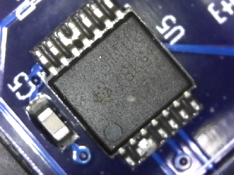
What does that chip (the miss soldered one) on the expansion board do? Is it something that has to be repaired or will I just lose part function of the expansion board?
-
That chip on the expansion breakout board drives the servo outputs.
Have you used the M584 command to remap axes to the external drivers? Please share your config.g file.
Using the expansion board in either of the ways I received, you do not need R1 in the M569 commands.
-
This if what I have for a set up where using 3 connected pairs.
; General preferences
G90 ; Send absolute coordinates...
M83 ; ...but relative extruder moves; Network
M550 P"My Printer Rev A" ; Set machine name
M551 P"Chickenprint" ; Set password
M552 S1 ; Enable network
M587 S"Netgear34" P"Chickenprint" ; Configure access point. You can delete this line once connected
M586 P0 S1 ; Enable HTTP
M586 P1 S0 ; Disable FTP
M586 P2 S0 ; Disable Telnet; Drives
M569 P5 S1 ; Drive 5 goes forwards
M569 P6 S1 ; Drive 6 goes forwards
M569 P7 S1 ; Drive 7 goes forwards
M569 P3 S1 ; Drive 3 goes forwards
M584 X5 Y6 Z7 E3 ; Apply custom drive mapping
M350 X16 Y16 Z16 E16 I1 ; Configure microstepping with interpolation
M92 X200.69 Y200.69 Z209.69 E420.00 ; Set steps per mm
M566 X900.00 Y900.00 Z12.00 E120.00 ; Set maximum instantaneous speed changes (mm/min)
M203 X1200.00 Y1200.00 Z1200.00 E1200.00 ; Set maximum speeds (mm/min)
M201 X500.00 Y500.00 Z20.00 E250.00 ; Set accelerations (mm/s^2)
M906 X800.00 Y800.00 Z800.00 E800.00 I30 ; Set motor currents (mA) and motor idle factor in per cent
M84 S30 ; Set idle timeout; Axis Limits
M208 X0 Y0 Z0 S1 ; Set axis minima
M208 X400 Y400 Z400 S0 ; Set axis maxima; Endstops
M574 X1 Y1 Z1 S1 ; Set active high endstops; Z-Probe
M558 P5 H5 F120 T6000 ; Set Z probe type to switch and the dive height + speeds
G31 P500 X0 Y0 Z2.5 ; Set Z probe trigger value, offset and trigger height
M557 X15:20 Y15:195 S20 ; Define mesh grid; Heaters
M305 P0 T100000 B4138 R4700 ; Set thermistor + ADC parameters for heater 0
M143 H0 S120 ; Set temperature limit for heater 0 to 120C
M305 P1 T100000 B4138 R4700 ; Set thermistor + ADC parameters for heater 1
M143 H1 S280 ; Set temperature limit for heater 1 to 280C; Fans
M106 P0 S0.3 I0 F500 H-1 ; Set fan 0 value, PWM signal inversion and frequency. Thermostatic control is turned off
M106 P1 S1 I0 F500 H1 T45 ; Set fan 1 value, PWM signal inversion and frequency. Thermostatic control is turned on; Tools
M563 P0 D0 H1 ; Define tool 0
G10 P0 X0 Y0 Z0 ; Set tool 0 axis offsets
G10 P0 R0 S0 ; Set initial tool 0 active and standby temperatures to 0C; Automatic saving after power loss is not enabled
; Custom settings are not configured
-
You haven't used the T parameter in the M569 commands to lengthen the step pulse timing for your external drivers. But the motors should still lock because of the Enable signal as soon as you try to move them. How are you trying to move them? Are you sure there are no "not homed" or similar error messages?
-
I can freely move the lead screw by hand (only a little since I know the feed back could destroy drivers). There is also no audible noise (usually is a engaging noise on other boards when they power up). I have tried to use the M564 H0 to command to move as well. I have also used a T5 setting in the past still nothing. The motors are wired correctly since they do work on the drivers provided on the board. I have even used the same wires to connect to a MKS base board and the drivers work with the configuration. Is there any type of test with the multi meter i can check to help narrow down some stuff?
Thank you! Much appreciated
-
Start by checking the voltage between E+ and E- on one of the expansion breakout board outputs. It should be -4V before you first try to move the motor, and +4V afterwards.
-
Will do when I get home. I was also thinking of testing a G540 (Gecko 4 axis drive) when I get home to eliminate a variable. The pin out only has a Step and Dir for each axis. How would you advise wiring this one? Im a little confused on this one because there is no enable pins
Pin 1 Output 2
Pin 2 X-AXIS STEP
Pin 3 X-AXIS DIRECTION
Pin 4 Y-AXIS STEP
Pin 5 Y-AXIS DIRECTION
Pin 6 Z-AXIS STEP
Pin 7 Z-AXIS DIRECTION
Pin 8 A-AXIS STEP
Pin 9 A-AXIS DIRECTION
Pin 10 INPUT 1
Pin 11 INPUT 2
Pin 12 INPUT 3
Pin 13 INPUT 4
Pin 14 VFD PWM (50HZ)
Pin 15 FAULT (INPUT TO PC)
Pin 16 CHARGE PUMP (>10KHZ)
Pin 17 OUTPUT 1
Pin 18 - 25 GND -
The G540 doesn't have optically isolated inputs, so you need to be very careful to have good ground wiring. If the ground wire between the Gecko and its PSU breaks, the motor current may try to find a path to ground through the 3.3V outputs of the Duet, which will wreck the Duet processor and more besides.
The G540 rev 8 user manual that I found says the minimum signal voltage is 3.3V, so it should work with the step/dir inputs connected directly to the Duet expansion bus. You would need to lengthen the step pulses using the M569 T parameter. As it has no Enable inputs, I presume it leaves the motors enabled continuously, possibly at reduced current when they are not moving.
-
Trying this configuration (directly to the expansion *no expansion board)
• Connect the 3 negative inputs of your drivers to ground on the Duet
• Connect the PUL+, Dir+ and EN+ inputs to E2_STEP, E2_DIR and E2_EN on the Duet
• Invert the enable signal using the R1 parameter of the M569 command for that driver in config.g.Results
Motors still will not lock and the drive will go into alarm when powered on.
** With everything the same except M569 P5 R0 – drive is fine until move is initialized then it goes into alarm. (still no motor lock)I’m still waiting for Filastruder to give me a replacement so I have been unable to try the other options using the expansion board.
I did try to connect my G540 drive. The motor did lock however when I sent a step signal it would click softly and not turn. The step units for this axis was set with “M92 X200.69 Y200.69 Z209.69 E420.00”
• Nothing was attached to motor during test
• Prior to connecting G540 to Duet this same wiring/stepper interfacing with mach3 control software with the G540 connected to the PC worked fine.
Please advise -
To get the M5045 working you will probably need to use the breakout board to increase the voltage and current drive to the external driver.
When driving any sort of external drivers, you must use the T parameter of the M569 command to lengthen the step pulse timings. The step pulses generated by default are very short and fast, which is no problem for the internal drivers but too fast for most other drivers.
-
Sorry I forgot to add, I did add T5 to the command. How high can the T value go before its maxed?
Just thinking out loud, could the firmware possibly play a role in the issue I am having with external drivers? I updated the firmware to the latest release (non beta) before I started wiring. I noticed not too many people use external drives (as I could not see many examples online to try and copy from), maybe there is an earlier firmware I should try that absolutely works? Im using v2.02 right now.
Still waiting on Filastruder to ship a replacement board to try out the expansion board again.
Thank you for your time!
-
Lots of Duets users are using external drivers. If there was a problem with external drivers in 2.02, I'm sure we would know about it.
Please post the config.g file that you are using to try to get the G540 driver working.
-
Finally I had time to work on my 3d printer :)! I was able to get response from the G540 adjusting the T value (Thank you!) but can only get 1 axis to work at a time.
Currently I have the STEP(+) and Dir(+) pins connected to their respective pins on the G540. I also have the STEP(-) and Dir(-) connected to a ground pin on the G540. The driver will work great when only 1 axis is connected, when the other 2 axis are connected along with the first nothing happens. From what I observed, the wiring only works when I connect a wire coming from STEP/Dir (-) pins to ground on the G540. It appears that this wiring can only have 1 axis connected back to ground on the G540. If I have multiple axis connecting it gets a mixed signal I'm guessing and will not move any of them.
So I guess my question would be, how do I properly wire STEP/DIR(-) to the G540 where all axis will work when connected at once?
This setup is using the expansion board.
-
Do not connect any of the output pins of the expansion board to ground. They are all differential outputs, so doing so may burn out the driver chips on the expansion board. Instead, connect GND on the G540 to GND on the Duet, or to GND on one of the servo output connectors on the expansion board.