PT100 better wiring and software M305 settings
-
@dc42
Thanks for coming back on this!
I have also some news:- Phoned around and found a nice company that is reseller of "daitron"-PSUs and they gave me a test unit for which they will only charge me if I keep it, put it in on the weekend and have to say: It is MUCH better then anything I have known before of... they are "bloody" expensive, but since the printer is not for me I have to bite that apple... at least it is a test-unit for which I get a discount...
- new twisted-pair-moving-application-shielded-cable for the extrudermotor that is close to the heater-sensor (...direct-drive-setup...) will arrive this week
")
Question:
- A friend advised me to extensivly use M84 whereever I can and this works great! BUT: I have the feeling that with the latest firmware, M84 will also kick out any homing done if it is used for X/YorZ on a cartesian... (I can only turn off E0=a.k.a. "the problem motor", all other motors (in my case of course only Z) to "1"% idle-hold which is "at least 100mA" quoted from https://duet3d.dozuki.com/Wiki/Gcode#Section_M906_Set_motor_currents) -> So could this in the next releases be able to lower it even more (at least for the extruder-motors for direct-drive-setups with noise-problems like mine), that if somebody forgets to call M84 E0 it will automatically be lowered even below 100mA...?
-
@dc42 said in PT100 better wiring and software M305 settings:
Twisted pair wiring for the stepper motors may help, but you must use one pair for each motor phase. The wiring for the step/dir/en signals between the breakout board and the external drivers is not critical, assuming that the external drivers have the usual optically isolated inputs.
Is your PSU definitely adequate for those external stepper drivers plus the heaters?
"Old" one was 1000W, new "Daitron" is 300W, so let´s calc for the new one:
- 65W heater (M84 E0 is called when heating up and no movement in x, y & z)
- 2,4A in Z = 57,6W -> But with M906 I1 it always get´s down to those 100mA...
- ca. 0,8A for E = 19,2W -> But with M906 I1...
= 141,8W so far
- fans
- duet
not more than 200W?
-> So in worst-case the external-drivers have 100W left, each 50W...
-> external steppers have also current-reduction on standstill which is "auto"(matic) and I have to find out how much it is... and how much they suck in worst case...
checking this numbers I also could have taken your expansion-board (ha!) if I only knew before I would have ended up with those 300W... -
@lb said in PT100 better wiring and software M305 settings:
A friend advised me to extensivly use M84 whereever I can and this works great!
Ignore that. It may be true for Marlin and other ancient firmwares, and for any electronics that doesn't have software-controllable stepper motor current; but it's not true for RepRapFirmware/Duet. RRF reduces the stepper motor current to the idle percentage when all motors have been idle for the idle time. The idle current and idle time default to 30% and 30 seconds, but they can be changed in the M906 command. The idle current is enough to hold the motor positions, but reduces the power consumption and heat generation. Whereas if you disable motors using M84 or M18, then when you power them up again they may jump to a new position 4 full steps from the one they were in when you powered them down. That's one of the reasons why dual Z motors get out of sync, and it's why RRF flags motors as not homed when you turn them off using M18 or M84.
Powering motors down at the end of a print is OK if you home the printer before each print, and either you don't have dual Z motors or you do but you drive them independently and level them before each print.
On delta printers it is sometimes necessary to increase the idle current to around 60% in order to maintain motor position.
Duet WiFi hardware designer and firmware engineer
Please do not ask me for Duet support via PM or email, use the forum
http://www.escher3d.com, https://miscsolutions.wordpress.com -
Also stumbled across this, and will order there a pt100 just to be sure:
https://forum.duet3d.com/topic/4966/highly-erratic-temperature-readings-above-certain-temperature/7They have PT100 with shielding-cable provided and even offer 4wiring all the way to the actual sensor! Sadly the shortest length is 30mm with 3mm diameter but will have to try that...
Curious:
The best setup so far (faaaaar from perfect) is having a connection wire from GND-with-1MOhm-to-PT100shield & the motorshields on PE!
Having all shields either on GND (of course with those 1MOhm) or on PE makes things worse.
?
-
@dc42 said in PT100 better wiring and software M305 settings:
@lb said in PT100 better wiring and software M305 settings:
A friend advised me to extensivly use M84 whereever I can and this works great!
Ignore that. It may be true for Marlin and other ancient firmwares, and for any electronics that doesn't have software-controllable stepper motor current; but it's not true for RepRapFirmware/Duet. RRF reduces the stepper motor current to the idle percentage when all motors have been idle for the idle time. The idle current and idle time default to 30% and 30 seconds, but they can be changed in the M906 command. The idle current is enough to hold the motor positions, but reduces the power consumption and heat generation. Whereas if you disable motors using M84 or M18, then when you power them up again they may jump to a new position 4 full steps from the one they were in when you powered them down. That's one of the reasons why dual Z motors get out of sync, and it's why RRF flags motors as not homed when you turn them off using M18 or M84.
Powering motors down at the end of a print is OK if you home the printer before each print, and either you don't have dual Z motors or you do but you drive them independently and level them before each print.
On delta printers it is sometimes necessary to increase the idle current to around 60% in order to maintain motor position.
Ah - O.K., so I just put 10% within M906 but left the 1Second for Idle-timeout...
The printermechanics are build in a way that everything is geared and is pre-tighted, so nothing moves without force applied, so those 10% should be enough for the motors, maybe if I get the problem away I will put the idle-current higher again.What came to my mind:
- Do you know if thermistors of Typ-K-sensors are "more stable" then the PT100 with those ca. 2,5Meters of cable?
- Would it have a positive effect if I order a duex5 and put ALL motors to the duex5 and have everything else on the "main"-board? (I saw that the latest revision >9.0 has added capacitors on the steppers "for reduced EMI"...)
-
@LB, PT100 sensor should be stable if our wiring guidelines are followed. But I'm looking at whether adding extra capacitors on the PT100 board might make it more resistant to interference. If it does, then it will be possible to retrofit the capacitors. We'll also add a cable shield grounding point to the next revision of the PT100 board.
I don't think it's worth you getting a DueX unless you need more than 5 stepper motors.
Duet WiFi hardware designer and firmware engineer
Please do not ask me for Duet support via PM or email, use the forum
http://www.escher3d.com, https://miscsolutions.wordpress.com -
@dc42
(I tried 3 diffrent cables from straight-shielded over ethernet-shielded to "2x2x0,5 unitronic FD CP (TP) plus" -> Tomorrow will arrive a "double shielded"-cable "Li2Y(C)H-C11Y 2x2 AWG24" from "metrofunk kabel union", means each twisted pair is shielded and also the whole cable... thinking about checking all cables for a bad contact, so far I only did the "beep"-measure-through to make sure to not have any short between one to the next internal cables but maybe that was not enough?)I have put "M143 H1 S350 A2" into the "config.g" to see, if there is a failure with the heater, that way, I could print on maybe...
Sounds interesting with that new board
- when will it be available, or can I become a beta-tester within 2weeks? Out of curiosity: Are you planning to include those capacitors on the motordrivers from the duex5-0.9 into the next duet2-v1.0.5 or are they already there?Another thing to test for me: Would anything bad happen if I leave X&Y as external motors in the config.g but (when machine is powered off) I pull the flat connector-cable and make it on to see if some of the noise is gone?
-
@lb said in PT100 better wiring and software M305 settings:
Out of curiosity: Are you planning to include those capacitors on the motordrivers from the duex5-0.9 into the next duet2-v1.0.5 or are they already there?
They are already included in recent Duet revisions. https://duet3d.dozuki.com/Wiki/Hardware_Overview#Section_PCB_revision_v1_Num_02
Duet WiFi hardware designer and firmware engineer
Please do not ask me for Duet support via PM or email, use the forum
http://www.escher3d.com, https://miscsolutions.wordpress.com -
SOLVED:
With "M143 H1 S350 A2" where exactly should it give me the possibility to reset a heater-fault without restarting?
"A Action to trigger (0: Generate heater fault [default] 1: Switch off permanently 2: Switch off temporarily)"Question not solved:
And would M18 instead of M84 to disable at least E0(extrudermotor in the direct-drive-setup close to the PT-100) do any good or is there a diffrence?Edit (question out of curiosity) -think it is somehow solved(?):
(If we pause in the middle of a heat-up-process, will it just keep on heating to active-/standby-temperature or will it pause also the heatup and swap the target-temp with whatever it currently has? Just asking because of the time given within "M570" could interfere here? -> Thinking about it it does not matter, if after setting a temperature pause is pressed just before that m116 to wait for it, in both cases it heats up to the set temperature...(?)) -
To reset a heater fault without restarting, simply enter M562. No other parameters are needed and this will clear a heater fault on all heaters
-
@ayudtee said in PT100 better wiring and software M305 settings:
M562
Thanks! Cool! (ahrgh sometimes it could be so easy...
)@dc42
@ayudtee
Seems I understood M570 also wrong... I have put now "M570 P8 S15" there what should help (overlooked that from RRF>=1.2 S are minutes and not seconds...)The twisted cable for the direct-drive arrived but did not change anything
 at least the motor is now more immune to EMI though this wasn´t my problem exactly...
For the sake of tried to disable all non-used extruder drives, e.g. "M569 P4 R-1", but that didn´t do it either
I guess I call it a day... -
Hi,
tried to take away all cables today but the PT100: Long story short: It does not matter what is connected to the duet, the error on the PT100(-cable/-connector/?) is still there. Since I made 3 cables the last weeks as written earlier, as of today with the other stuff removed helping nothing, my next thing to test is if the PT100 could have a loose contact somewhere or is internally broke. Just ordered a new one. This brought me to the point to think about the daughter-board, so I went to the website to the MAX31865 and it says there:
"Fault Detection (Open RTD Element, RTD Shorted to Out-of-Range Voltage, or Short Across RTD Element) "
If I - hey easter has arrived - have still maybe a wish to add to the wishlist: In that possible next revision of the PT100-board you wrote of which might be more immune to EMI, could you make those "fault detections" more accesible to the console, to be able to have a better understanding of the error... just dreamin a bit here with my problem still unsolved... I am sure there is a lot of other things to do with the duet3 around the corner...My new PT100 (1 from e3d, 1 from sensorshop24) will arrive next week so hopefully I can track down the error more precise then (have no connector left for the e3d(molex?)-connector on the PT100 to just directly plug it into the board and test it with my hands or a soldering iron (it was stupid that I directly put the connector to my own 3meter cable instead of first testing the arrived sensor in the original state)... also seems to be a quite little plastic connector that e3d choose, maybe I swap it with a diffrent heavy-duty- one to make sure it is not the connector...
Smartest idea so far maybe:
Another thing that came up my mind: Within M307 of the heating-process-parameters the Fnnn-PWM-Freq-paramter: Is there a PWM-Freq that would be ideal regarding lowest possible noise for the MAX31865 and what would that frequency be? (I have read for external boards:"The communication between the Duet and the RTD interface board uses 4MHz SPI signalling, so the wires should be kept short" but that should not be any problem if using the duet-daughter-board directly connected I gues... I have not checked with which frequency the MAX31865 works on the PT100-line?) Would it be as simple as choosing an uneven divider that will never be in harmonic, I guess no (?), it will be more complex? As usual I assume you already thought about it and the default-PWM-Freq is already optimized for it... just have to ask
-
@lb said in PT100 better wiring and software M305 settings:
If I - hey easter has arrived - have still maybe a wish to add to the wishlist: In that possible next revision of the PT100-board you wrote of which might be more immune to EMI, could you make those "fault detections" more accesible to the console, to be able to have a better understanding of the error
There are already ways to get that message:
-
If the error occurs immediately, then it will be reported when you send the M305 P1 X200 command.
-
In the 2.03beta firmware, sending M305 P1 will report (amongst other things) the last error reported by the sensor.
Another thing that came up my mind: Within M307 of the heating-process-parameters the Fnnn-PWM-Freq-paramter: Is there a PWM-Freq that would be ideal regarding lowest possible noise for the MAX31865 and what would that frequency be?
There is already an option in the M305 command to reject either 50Hz or 60Hz mains frequency. You could set the heater PWM frequency to be the same.
Duet WiFi hardware designer and firmware engineer
Please do not ask me for Duet support via PM or email, use the forum
http://www.escher3d.com, https://miscsolutions.wordpress.com -
-
@dc42 said in PT100 better wiring and software M305 settings:
@lb said in PT100 better wiring and software M305 settings:
If I - hey easter has arrived - have still maybe a wish to add to the wishlist: In that possible next revision of the PT100-board you wrote of which might be more immune to EMI, could you make those "fault detections" more accesible to the console, to be able to have a better understanding of the error
There are already ways to get that message:
-
If the error occurs immediately, then it will be reported when you send the M305 P1 X200 command.
-
In the 2.03beta firmware, sending M305 P1 will report (amongst other things) the last error reported by the sensor.
Another thing that came up my mind: Within M307 of the heating-process-parameters the Fnnn-PWM-Freq-paramter: Is there a PWM-Freq that would be ideal regarding lowest possible noise for the MAX31865 and what would that frequency be?
There is already an option in the M305 command to reject either 50Hz or 60Hz mains frequency. You could set the heater PWM frequency to be the same.
Thanks (!): Set with "M307 H1 F50" in the config.g now. (for the PT100 you already suggested that to me a long time ago
)I cannot judge if this helped but maybe a little bit (at least psychologically) If asking after powerup with M307 H1, it throws back 50Hz, so this should be working now. (Though I have the feeling it got louder now, but hey, that is the price I guess)
50Hz for the fans would be too low I guess, so would multiples of 50Hz be of any benefit for the fans then regarding the noise-issues on the PT100, e.g. 100Hz or similar, because judging by this post here https://forum.duet3d.com/topic/5248/maximum-frequency-of-pwm-fans/5 I have the option to have low frequency with my current 2-wire-fans OR get 4wire-fans and rewire them...
-
-
Your fans may be noisy at 50Hz, but you could try 100Hz or 200Hz.
Duet WiFi hardware designer and firmware engineer
Please do not ask me for Duet support via PM or email, use the forum
http://www.escher3d.com, https://miscsolutions.wordpress.com -
Are you considering voltage-dimming on the duet3 or maybe a daughter-board of duet3? Doing the electronics yourself would be a lot of work it seems, but you could hack (although very inefficient) a resistor-bank (like on those high-end-audio-gear but for sure to inefficient and costly - I am sure you know better than me) or (alternative-)use e.g. LED-drivers like the "recom RCD-24/PL", that I played with a long time ago on a LED-project that allow PWM-/Voltage-/combined-dimming... just do not know what they would do to a fan ( (?) would have to check... for sure you can judge better than me)
- but I do not know (yet maybe never) enough about electronics to sufficiently be able to write something meaningful here -
Since you already leaked the information that you consider a 4-pin-fan-port on some new board maybe, that is maybe enough for me, and since I have 1 always-on-fan free (1 is used to cool the mainboard) I will try maybe the trick from the other post
At least learned something: If going so far as replacing also the heater and fan cable that are close to the PT100, at least for the fan will get a (TP of course) 4-wire-cable to be able to sooner or later fit a 4-pin-fan there -
On my delta I have a Smart Effector with PT100 sensor and 8 core unshielded cable from the Smart Effector back to the Duet, which includes the 4 PT100 wires. In the same bundle (which is 500mm long) is another 8 core unshielded cable that powers the hot end heater and 2 fans. I have never had a problem with the reading from the PT100.
Stepper motor cables are much more likely to cause interference.
Duet WiFi hardware designer and firmware engineer
Please do not ask me for Duet support via PM or email, use the forum
http://www.escher3d.com, https://miscsolutions.wordpress.com -
@dc42 said in PT100 better wiring and software M305 settings:
On my delta I have a Smart Effector with PT100 sensor and 8 core unshielded cable from the Smart Effector back to the Duet, which includes the 4 PT100 wires. In the same bundle (which is 500mm long) is another 8 core unshielded cable that powers the hot end heater and 2 fans. I have never had a problem with the reading from the PT100.
Stepper motor cables are much more likely to cause interference.
Yeah - I am cursed I guess... If the new PT100-sensor arrives mid of the week and the old one was the problem, the company that makes them owns me one for free
(happened before it seems: https://forum.duet3d.com/topic/4966/highly-erratic-temperature-readings-above-certain-temperature/7)Will also check this: https://forum.duet3d.com/topic/252/spurious-heater-faults-and-how-to-avoid-them/37
But to be honest with all those little tweeks from the last weeks the spikes are now so erratic and seldom, that a print almost never fails, just working on the "almost" now
I am definetly over 90%, maybe 95% and I consider my job done if one out of 100 readings is erratic... with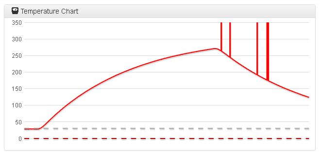
The lower frequencies like 50hz were actually the opposite of beneficial, I am back at multiples of 50, around 300 now, and that is also what you can see in the screenshot of the auto-PID-tuning (with lower frequencies it looked much worse). With "M570 P9" it works fine, just would like to lower P9 to P7 or so
disabling unpopulated steppers and fans did not do any change (assumed it wouldn´t ) could you give me a hint how to disable the unpopulated 2nd heater for now, if you do not do that already in your firmware I guess
EDIT: found it, "allow the PID controller for a heater to be disabled by setting the A, C and D parameters to -1" but as you said, it didn´t change anything -
Unused heaters and extruders won't generate any interference, until you command them to turn on.
Duet WiFi hardware designer and firmware engineer
Please do not ask me for Duet support via PM or email, use the forum
http://www.escher3d.com, https://miscsolutions.wordpress.com -
Relief-time: The spikes where because of a bad connector! Beside of electrostatic-discharge-triggered-spikes when e.g. calibrating the z-offset while interfacing with hand (wearing the wrong shoeds or shirt) with the print-head I had no more spikes so far -> and when doing that whoever does it could wear gloves if it should be really a problem.
Now will check if I can revert back to the old switching-power-supplyEdit (a few days later): Just remembered that I had a test where I removed all cable but the PT100 and still the 2000C was there -> Since I vacuumcleand the thing the last days and found a little metal-debris from the work on the gantry I rather thing there where some fine metal-flakes that were responsible for the whole problems.
-> What I learned: There is a reason why usually the electronics is not mounted underneath a gantry which is made of metal but rather at the "back", because when you work on the metal the chances are smaller that debris "falls" into the electronics-bay.