Duet2 and yl620 vfd, chinese spindle control
-
0_1560104764901_YL620-A.pdf
I bought the name yl620-a vfd. I want to control the yl620 vfd on the duet2 board. Please tell me how.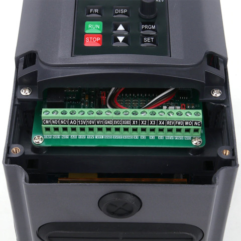

-
You should be able to configure a Duet Servo output to do this? I am not an expert, but I came across this video recently:
-
I have a similar looking PWM to 0-10V converter connected as follows:
- DIN- - FAN1-
- DIN+ - V_FAN
- 12-30V - the Duet power supply
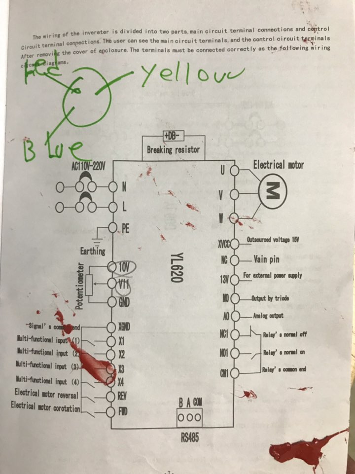
- AO/A0 - the VFD VI pin (VI1 in your case)
- GND - the Duet power supply and the GND pin on the VFD (can also be named ACM)
Set the PWM input signal level to 24V or you might break the optical coupler at its input.
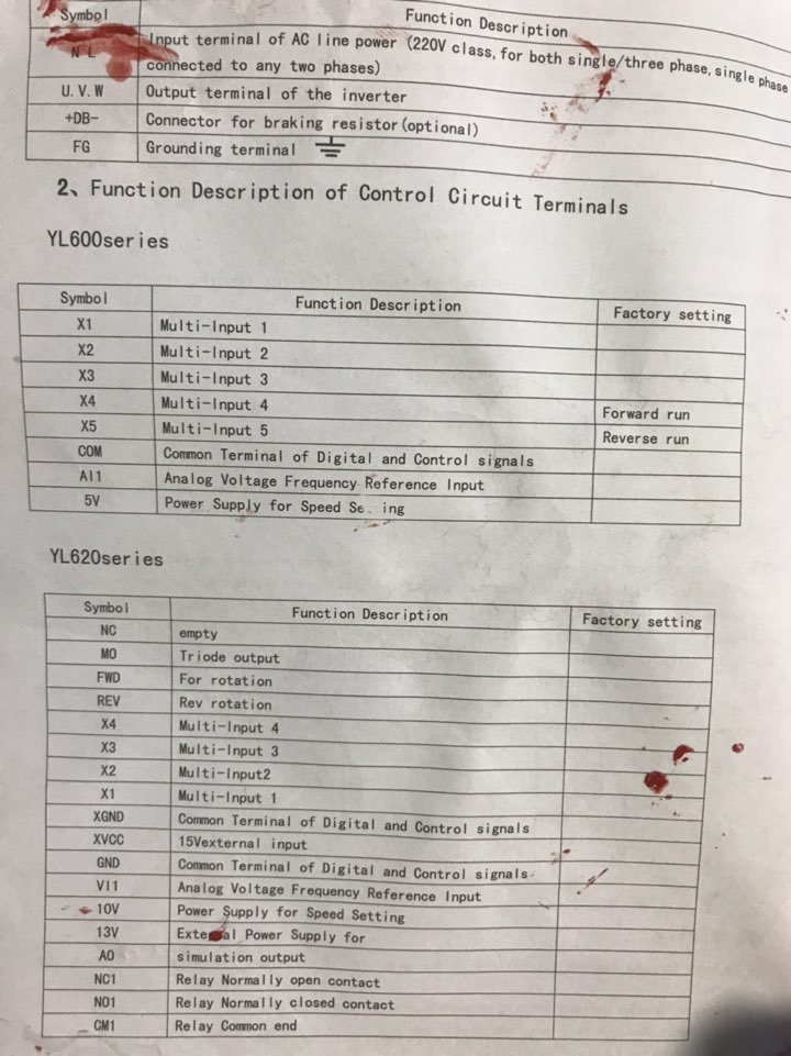
On the VFD you also need to short FWD (can also be named FOR) to XGND (can also be named DCM or COM).
Enable the spindle on FAN1 output by adding the following into the config.g script, replacing the R24000 parameter with the maximum speed of your spindle:
M453 P21 R24000 F1000
M563 P2 S"Spindle"Specify in the post-processor of the CAM software:
- M3 {$s} G4 S30 for spindle start - this is for CamBam, for other CAM software the {$s) variable might look differently; adjust the S30 to allow the spindle reach maximum speed before plunging into the material.
- G4 P0 M5 for spindle stop - the default M5 doesn't wait for all movement to finish!!!
Check in the VFD manual for P00.01 and P07.08. They both need to be properly set in order for the VFD to use the signal on VI1 for speed control. In case of Huanyang VFDs, check PD001and PD070.
The VFD might also have some small switches near the control terminals connector, usually undocumented.
I also have a spindle warmup macro that I run before doing the first machining of the day, as you need to get the grease fluid enough for top speed:
M3 S5000 G4 S120
M3 S10000 G4 S120
M3 S17000 G4 S120
M3 S24000 G4 S120
M5With the above, the spindle RPM will be correct at top speed, being 10-20% higher at lower RPMs.
-
O@catalin_ro hi there, a fantastic post. I was quite far in the build, but now I made some more steps.
I can control 1-10v signal.
I can control the rpm.I just can't control the motor from starting or stopping. It always keeps spinning at 6000rpm. 6000 is the bottom programmed speed, should I reduce this to 0 or is there another parameter that i need to change? I would love to hear back from you.
Kind regards,
Alexander
-
@yesealex Reduce the minimum speed to 0 and consider the limit when generating the GCode files with the CAM software. I have myself an 800W spindle, air cooled, and it is also specified for minimum 6000RPM, but I have used it at speeds as low as 4000RPM, just that only for brief periods of time. Lower speeds are usually not justified as they are usually specific to much larger tools, way beyond what a 2.2kW spindle can handle.
Alternatively, a separate CW/FOR/FWD pin would need to be used and I have not tested this solution so far!
-
@catalin_ro hi!
Once again thank you for the response. Which parameter would control the minimum frequency? PD011?
Thanks for the help.
Kind regards,
Alexander -
@yesealex hi!
Yes, PD011 seems to be. I have changed on my VFD only the parameters that I really needed to change.
-
@catalin_ro hi there! I just managed to re program the vfd and this now works! It is awesome!
Thanks for all the help,
Alex