Delta X and Y head position change during Z autocalibration
-
Hello
I am trying to calibrate the delta printer with Duet2Wifi + Delta Smart Effector + Haydn Magball Rods, following this document:
https://duet3d.dozuki.com/Wiki/Calibrating_a_delta_printer
I send the head to various xy coordinates of my circular 240mm bed (the delta frame is from an Anycubic Kossel Linear Plus), with the Z coordinate at about 5 mm above the bed. In that position, I execute
G30 S-1
4 or 5 times, to get multiple readings of the same xy spot, and to make sure the readings are consistent.
Well, in the web UI I see that the X and Y coordinates of the nozzle changes during those 4-5 probes.
For instance
Heat the nozzle to 210C and the bed to 100C;
G90
G1 x0 y0 z5
; now run the following sequence of two commands 4-5 times
G30 S-1
G1 Z5then look at the top-left in the web UI. The X and/or Y did not keep their initial position, and also the final value of Z is not 5.
I did the test for x0 y0 and for other 6 points along the edge of the circular bed (which has 240 mm diameter)
The results are
G1 X0 Y0 Z5
; average value for the "Stopped at height message" logged in the GCode console is -0.181 mm
; final position of the head shown in web GUI after 5 z probes is: x = 0, y = 0.08, z = 4.84G1 X0 Y-109 Z5
; average value for the "Stopped at height message" logged in the GCode console is +0.170 mm
; final position of the head shown in web GUI after 5 z probes is: x = 0, y = -108.94, z = 5.19G1 X0 Y+110 z5
; average value for the "Stopped at height message" logged in the GCode console is +0.674 mm
; final position of the head shown in web GUI after 5 z probes is: x = 0 , y = +110.06, z = 5.57G1 X-95 Y+64 z5
; average value for the "Stopped at height message" logged in the GCode console is +0.094 mm
; final position of the head shown in web GUI after 5 z probes is: x = -94.98, y = 64.06, z = 5.12g1 X96 y64 z5
; average value for the "Stopped at height message" logged in the GCode console is +1.151 mm
; final position of the head shown in web GUI after 5 z probes is: x = 95.98, y = 64.07, z = 6.18g1 X96 Y-64 z5
; average value for the "Stopped at height message" logged in the GCode console is +0.741 mm
; final position of the head shown in web GUI after 5 z probes is: x = 96, y = -63.92, z = 5.77g1 X-95 Y-64 z5
; average value for the "Stopped at height message" logged in the GCode console is -0.076 mm
; final position of the head shown in web GUI after 5 z probes is: x = -95, y = -63.92, z = 4.91Is it normal for the x, y and z values to deviate from their theoretical positions ?
I have 0.9 degrees stepper motors 42BYGHM810 with 20-teeth pulleys and GT2 belts. My config.g is below.
G90 ; Send absolute coordinates...
M83 ; ...but relative extruder moves
M665 R138 L288.14:288.14:288.15 B120 H205 ; Set delta radius, diagonal rod length, printable radius and homed height
M666 X0 Y0 Z0 ; Put your endstop adjustments here, or let auto calibration find them; Network
M550 P"..................." ; Set machine name
M552 S1 ; Enable network
M587 S".............." P"........................" ; Configure access point. You can delete this line once connected
M586 P0 S1 ; Enable HTTP
M586 P1 S0 ; Disable FTP
M586 P2 S0 ; Disable Telnet; Drives
M569 P0 S1 ; Physical drive 0 goes forwards
M569 P1 S1 ; Physical drive 1 goes forwards
M569 P2 S1 ; Physical drive 2 goes forwards
M569 P3 S1 ; Physical drive 3 goes forwards
M350 X16 Y16 Z16 E16 I1 ; Configure microstepping with interpolation
M92 X160.00 Y160.00 Z160.00 E145.51 ; Set steps per mm
M566 X1200.00 Y1200.00 Z1200.00 E1200.00 ; Set maximum instantaneous speed changes (mm/min)
M203 X18000.00 Y18000.00 Z18000.00 E1200.00 ; Set maximum speeds (mm/min)
M201 X3000 Y3000 Z3000 E3000 ; Set accelerations (mm/s^2)
M906 X1000.00 Y1000.00 Z1000.00 E800.00 I30 ; Set motor currents (mA) and motor idle factor in per cent
M84 S30 ; Set idle timeout; Axis Limits
M208 Z-0.1 S1 ; Set minimum Z; Endstops
M574 X2 Y2 Z2 S1 ; Set active high endstops; Z-Probe
; M558 P5 R0.4 H10 F1200 T2400 ; Set Z probe type to effector and the dive height + speeds
M558 P8 R0.4 F1200 T6000 X0 Y0 Z0 H3 ; Z probe is a Smart Effector and is not used for homing any axes R0.4 not used. Reduced F300 to 100
G31 P100 X0 Y0 Z-0.2 ; Set the zprobe height and threshold for Smart Effector
M557 R110 S20 ; Define mesh grid; Heaters
M307 H0 B0 S1.00 ; Disable bang-bang mode for the bed heater and set PWM limit
M305 P0 S"bed240mm" T85000 B3950 R4700 H30 L0
M143 H0 S120 ; Set temperature limit for heater 0 to 120C
M305 P1 S"nozzle" X200 ; Configure PT100 for heater 1
M143 H1 S240 ; Set temperature limit for heater 1 to 240CM570 S180 ; Hot end may be a little slow to heat up so allow it 180 seconds
M307 H0 A135.0 C793.3 D0.9 S1.00 V23.8 B0
M307 H1 A622.9 C269.7 D5.6 S1.00 V23.8 B0; Fans
M106 P0 S0 I0 F500 H1 T45 ; Set fan 0 value, PWM signal inversion and frequency. Thermostatic control is turned on; Tools
M563 P0 D0 H1 ; Define tool 0
G10 P0 X0 Y0 Z0 ; Set tool 0 axis offsets
G10 P0 R0 S0 ; Set initial tool 0 active and standby temperatures to 0C; Automatic saving after power loss is not enabled
; Custom settings are not configured
; Miscellaneous
M501 ; Load saved parameters from non-volatile memory
T0 ; Select first toolThanks in advance
Mihai -
@mihaitintea said in Delta X and Y head position change during Z autocalibration:
M665 R138 L288.14:288.14:288.15 B120 H205 ; Set delta radius, diagonal rod length, printable radius and homed height
I have an AKL+ with a Duet and Smart Effector. SLIGHTLY different rods, I happened to already have a set of 304s from Hayden when I built this printer.
M665 L304.190 R140.174 H202.010 B110.0 X0.436 Y0.226 Z0.000
Most of our settings are very close. I appear to be getting quite a bit more B (printable radius).
-
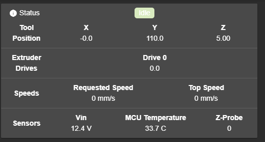
I ran the experiments you described at 0,0 and 0,110. ABSOLUTELY NO unexpected changes in X,Y on the DWC display. During the execution of the G30, I see what I'd expect, movement, probe hits, etc, etc.
So... not normal... don't know what's going on with yours.
Here's the dashboard, and the log:
7/13/2019, 4:46:03 PM G30 S-1 Stopped at height -0.403 mm 7/13/2019, 4:45:59 PM G1 Z5 7/13/2019, 4:45:59 PM G1 Z5 7/13/2019, 4:45:57 PM G30 S-1 Stopped at height -0.428 mm 7/13/2019, 4:45:53 PM G1 Z5 7/13/2019, 4:45:50 PM G30 S-1 Stopped at height -0.416 mm 7/13/2019, 4:45:44 PM G1 Z5 7/13/2019, 4:45:41 PM G30 S-1 Stopped at height -0.403 mm 7/13/2019, 4:45:37 PM G1 Z5 7/13/2019, 4:45:35 PM G30 S-1 Stopped at height -0.353 mm 7/13/2019, 4:45:27 PM G1 X0 Y+110 Z5 7/13/2019, 4:44:01 PM G1 Z5 7/13/2019, 4:44:00 PM G1 Z5 7/13/2019, 4:43:54 PM G30 S-1 Stopped at height -0.374 mm 7/13/2019, 4:43:49 PM G1 Z5 7/13/2019, 4:43:44 PM G1 Z5 7/13/2019, 4:43:39 PM G30 S-1 Stopped at height -0.374 mm 7/13/2019, 4:43:23 PM G1 Z5 7/13/2019, 4:43:23 PM G1 Z5 7/13/2019, 4:43:19 PM G30 S-1 Stopped at height -0.387 mm 7/13/2019, 4:43:07 PM G1 Z5 7/13/2019, 4:42:58 PM G30 S-1 Stopped at height -0.374 mm 7/13/2019, 4:42:33 PM G1 X0 Y0 Z5 -
The trilateration algorithm in firmware 2.03 is incorrect in the case that the first 3 rod lengths in the M665 command are not exactly the same. This probably explains your observation. So I suggest you set them all to be the same until I release 2.04RC1, which is imminent.
-
@dc42 said in Delta X and Y head position change during Z autocalibration:
bservation. So I suggest you set them all to be the same until I release 2.04RC1, which is i
Hello. Mr. DC42,
Thank your so much for your suggestion. Now the X Y values are perfectly constant during the execution of "G30 S-1".
Also I want to point out something about the autocalibration procedure https://duet3d.dozuki.com/Wiki/Calibrating_a_delta_printer, and I do that here because the forum topic
https://forum.duet3d.com/topic/5075/homed-height
is locked and I cannot post my thanks there.
That topic seems to be the only place in the whole duet3d website where I could find the following priceless piece of information about using Delta Smart Effector as a nozzle Z Probe:
"You should not need to use any H parameters on the G30 commands in bed.g when using the Smart Effector, or any other nozzle contact bed probe."
Oh, my, I wish I've found that info ages ago, that does not seem to pop out very clearly from the autocalibration procedure (https://duet3d.dozuki.com/Wiki/Calibrating_a_delta_printer). Maybe you could consider updating that document. Adding H corrections to the bed.g file made my iterative autocalibration attempts to diverge increasingly exponential, and my print head was always ramming into the X, Y or Z towers (my Hayden Magball rods didn't break yet, though !)
After putting H0 everywhere in the bed.g file, instead of whatever H corrections I found during my "G30 S-1" tests at various X Y positions, the autocalibration does not diverge exponentially any more. It always starts from values between 1 and 3-ish, and ends with a value less than 0.05. I cannot tell if successive autocalibration attempts can be called "convergent" because, here are 3 successive attempts:
Calibrated 6 factors using 16 points, deviation before 0.072 after 0.034
Calibrated 6 factors using 16 points, deviation before 3.062 after 0.034
Calibrated 6 factors using 16 points, deviation before 1.234 after 0.032Maybe I have a wrong understanding of the convergence concept, or maybe that could be another enunciation that may be corrected in the Duet documentation. Please can you give me feedback on this.
Anyway, many thanks with the recommendation about M665 L parameter.
Truly yours,
Mihai -
@mihaitintea said in Delta X and Y head position change during Z autocalibration:
Calibrated 6 factors using 16 points, deviation before 0.072 after 0.034
Calibrated 6 factors using 16 points, deviation before 3.062 after 0.034
Calibrated 6 factors using 16 points, deviation before 1.234 after 0.032There is a bug in firmware 2.03 whereby if the firmware updates the delta radius or the rod length, it adjusts the homed height incorrectly. I think that is what is happening in your case, and explains why the deviation went up from 1.234mm to 3.062mm before coming down again. This bug is fixed in the forthcoming 2.04RC1.