Help getting the magnetic filament sensor to power up
-
"Where is the LED on the magnetic filament sensor? The docs say the LED will flash when powered on but I don't see an LED anywhere.....Not sure if it is working or not. "
OK, I opened the thing up and found where the LED is....hiding in that little hole in the side is not obvious...however after applying power I still get squat...no LED nothing. I checked I have ground to the inside pin and 3.3v to the middle pin, the outside pin being the output. I have the cable attached to the E0 endstop connection. I added this config line to the config.g
M591 D0 P3 C3 S0 R70:130 E3.0 A1 L28.4
Does that look like it is correct? Even if it was wrong I should still get power. Did I get a defective sensor???
Anybody have any ideas I'd appreciate the help. Thanks
-
The LED shines (quite brightly) through a small cutout in the enclosure (its on the opposite side fomr the headers.
-
Are you sure you have the ground and output pins the right way round? The cable between the sensor and the endstop connector should be wired with the same pin order at both ends.
-
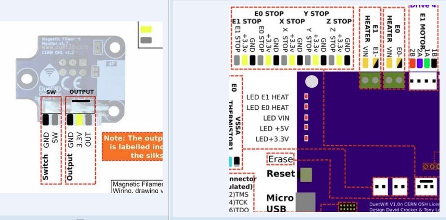
If the cable is pin to pin then one of these must be wrong....I have added the line to represent the index tab. These are both views from the top but according to these drawings the cable would have the outer pins flipped...wouldn't it? At least for it to go output to output and ground to ground.....The connector on the DUET has ground on the right and the sensor has the ground on the left...what am I missing?
-
@warpster I have updated that image again. very sorry about the confusion
-
Now it all makes more sense! Got the cable switched and it looks like I'm talking now. Thanks....
Also are the case STLs available so that those of us with sla printers could reprint them if needed...I notice the screw threads are just into the resin, no inserts, they won't last many times in and out...not that that is normally needed but..
-
@warpster yep, linked from the documentation:
https://duet3d.dozuki.com/Wiki/Duet3dFilamentMonitor_RotatingMagnetVersion#Section_Housing_models