Mesh calibration not working or what am I doing wrong?
-
I can’t figure out what I'm doing wrong.
The nozzle is too high on one side of the table and too close on the other.
Calibration during printing works - the table rises and falls when moving along the axes.
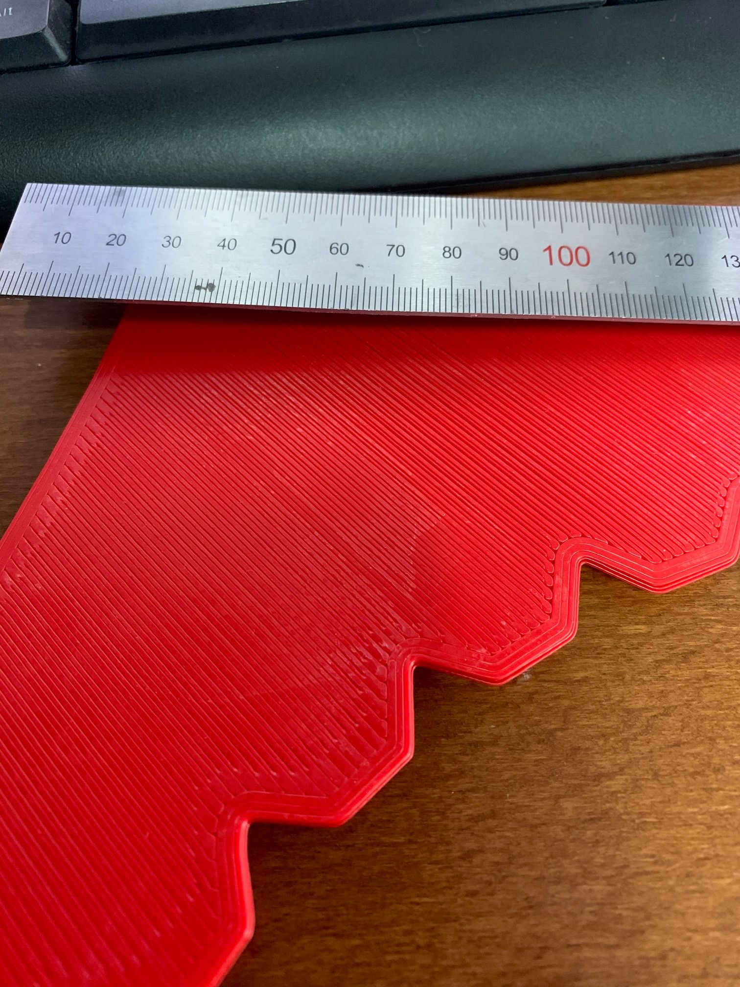
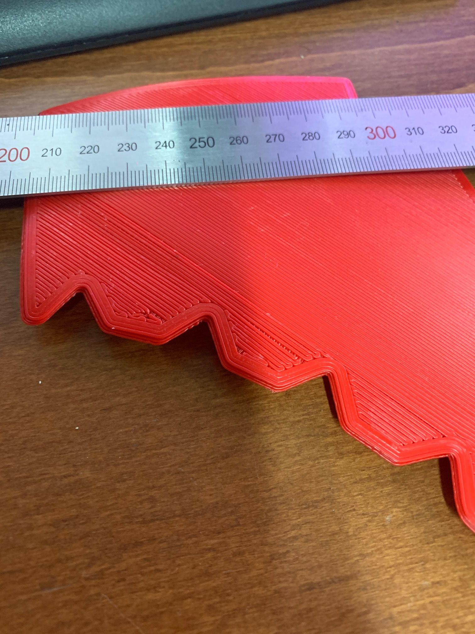
I attached a photo of the obtained first layer.
My configuration file:
; General preferences
M111 S0 ; Debugging off
M555 P2 ; Set firmware compatibility to look like Marlin

; Network
M540 PDE:AD:BE:EF:CA:66
M550 P1500 ; Set machine name
M552 P0.0.0.0 S1                         ; Enable network and acquire dynamic address via DHCP
M586 P0 S1                               ; Enable HTTP
M586 P1 S0                               ; Disable FTP
M586 P2 S0                               ; Disable Telnet

G21 ; Work in millimetres
G90 ; Send absolute coordinates...
M83 ; ...but relative extruder moves

;====M200 D1.75 ; set all extruder filament diameters to 1.75mm

; Endstops
M574 X1 Y1 Z1 S0 ; Define active low and unused microswitches
M574 E0 S0; BLTOUCH

; Drives ===
M569 P0 S1 ; Drive 0 goes forwards
M569 P3 S1 ; Drive 3 goes forwards

M584 X0 Y6 Z7
M569 P6 R1 T2.5:2.5:5 ; TB6600
M569 P7 S1 R1 T0.005 ;Z
M84 ;disabled drives
;== Power Z motor
G91
G1 Z0.2 S2
G90

; Steps, Speed
M566 X900 Y900 Z10 E800 ; Set maximum instantaneous speed changes (mm/min) ;NEW 2019
M203 X6000 Y6000 Z300 E6000 ; Set maximum speeds (mm/min)
M201 X1500 Y1500 Z300 E1500 ; Set accelerations (mm/s^2) ;NEW 2019

M906 X1500 Y0 Z0 E1200 I100 ; Set motor currents (mA) and motor idle factor in per cent
M84 S0 ;disable idle timeout; steppers will remain powered up regardless of activity

M350 X16 Y16 Z16 E16             ; set 16x microstepping
M92 X100 Y160 Z1600 E157 ; Set steps per mm

M208 X0 Y-35 Z0 S1 ; set axis minima только если минус - Z-0.5 ?
M208 X1380 Y1210 Z1500; Set axis maxima


; Heaters ====
; Duet0.8.5 uses 4.7K resistors

;Bed
M305 P2 T100000 B3950 R4700 H30 L0 X0
M307 H2 A90.0 C700.0 D10.0 S1.00 B1
M140 H2

; hotends
M305 P1 T100000 B3950 R4700 H30 L0 ; Set thermistor + ADC parameters for heater 0
M307 H0 A90.0 C700.0 D10.0 S1.00 B1
M307 H1 A418.9 C161.0 D3.2 S0.7 B0 ; 12 вольт

M143 S290 ; Set maximum extrudertemperature to 290C
M143 H0 S125 ; set the maximum bed temperature to 125C

M563 P0 D0 H1 ; Define tool 0
G10 P0 X0 Y0 ; Set tool 0 axis offsets
G10 P0 R0 S0 ; Set initial tool 0 active and standby temperatures to 0C

; Fans
M106 P0 S0 I0 F255 H-1; Set fan 0 value, PWM signal inversion and frequency. Thermostatic control is turned off (print cooling)
M106 P1 S0 I0 F255 H1 T60; Set fan 1 value, PWM signal inversion and frequency. Thermostatic control is turned on (extruder)

T0 ; Select first tool
M111 S0 ;

M141 H0 ; bed heater is the chamber heater
M305 P0 X2 R4700 T100000 B3950 ;термистор 2 экструдера
M301 H0 B1 ; use bang-bang control for the chamber heater


M581 E1 S1 T2 C1

; == PROBE
M307 H3 A-1 C-1 D-1 ; use pin 21 (PWM for heater 3)
M558 P9 H6 F300 T6000 R0.2 A5 B1
G31 P25 X27 Y-4 Z1.78 ; set probe height

; == MESH
;M557 X100:1300 Y120:1080 S120
M557 X500:1000 Y150:600 S25
M376 H6

M280 P3 S160 I1 ;Reset Probe Error State

M929 P"eventlog.txt" S1
bed.g file
M561 ; clear any bed transform
G29 S2 ; clear height map
G28 ; home all axes
G29 S2 ; clear height map
M84 E0
M564 S0
G29
homeall.g
G91                     ; relative positioning
G1 Z3 F600 S2          ; lift Z relative to current position
G1 S1 X-1500 Y-1640 F6000 ; move quickly to X and Y axis endstops and stop there (first pass)
G1 X5 Y5 F9000          ; go back a few mm
G1 S1 X-10 Y-10 F360  ; move slowly to X and Y axis endstops once more (second pass)

; + bltouch
G91               ; relative positioning
G1 Z3 F600 S2    ; lift Z relative to current position
; Back to absolute positioning
G90
; Go to first bed probe point and home the Z axis
G1 X750 Y580 F6000
G30
G29 S1 ; load a previously-generated height map using command G29 S1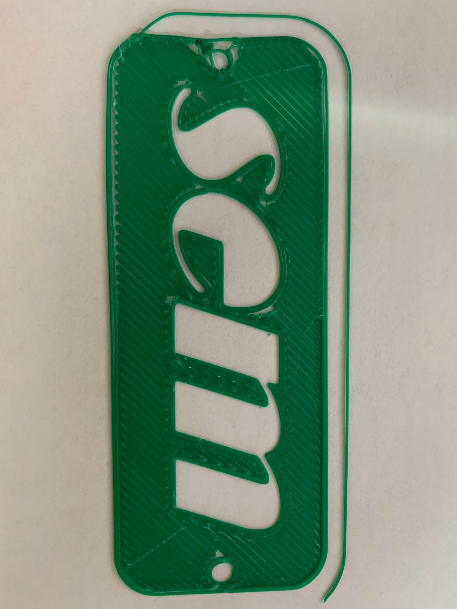
-
And my heightmap.csv
I probe only small part of the bed.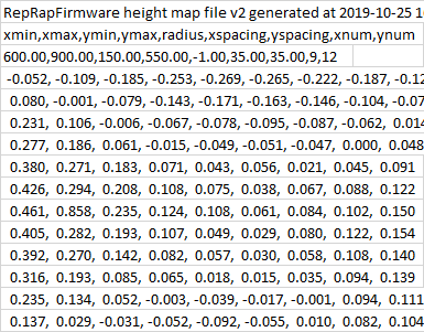 code_text ```RepRapFirmware height map file v2 generated at 2019-10-25 16:42, min error -0.269, max error 0.858, mean 0.065, deviation 0.164 xmin,xmax,ymin,ymax,radius,xspacing,yspacing,xnum,ynum 600.00,900.00,150.00,550.00,-1.00,35.00,35.00,9,12 -0.052, -0.109, -0.185, -0.253, -0.269, -0.265, -0.222, -0.187, -0.126 0.080, -0.001, -0.079, -0.143, -0.171, -0.163, -0.146, -0.104, -0.076 0.231, 0.106, -0.006, -0.067, -0.078, -0.095, -0.087, -0.062, 0.014 0.277, 0.186, 0.061, -0.015, -0.049, -0.051, -0.047, 0.000, 0.048 0.380, 0.271, 0.183, 0.071, 0.043, 0.056, 0.021, 0.045, 0.091 0.426, 0.294, 0.208, 0.108, 0.075, 0.038, 0.067, 0.088, 0.122 0.461, 0.858, 0.235, 0.124, 0.108, 0.061, 0.084, 0.102, 0.150 0.405, 0.282, 0.193, 0.107, 0.049, 0.029, 0.080, 0.122, 0.154 0.392, 0.270, 0.142, 0.082, 0.057, 0.030, 0.058, 0.108, 0.140 0.316, 0.193, 0.085, 0.065, 0.018, 0.015, 0.035, 0.094, 0.139 0.235, 0.134, 0.052, -0.003, -0.039, -0.017, -0.001, 0.094, 0.111 0.137, 0.029, -0.031, -0.052, -0.092, -0.055, 0.010, 0.082, 0.104 -
Hi,
Well for mesh-cal to work well you need to probe as much of the bed as you can.
Are you currently probing at least the area you are trying to print on?
Frederick
-
Yes. The model size on the photo is 150 x 30 mm. The size I am probe is 500 x 450 mm
The size of the whole bed is 1380 x 1210 mm
-
@Dep said in Mesh calibration not working or what am I doing wrong?:
The model size on the photo is 150 x 30 mm. The size I am probe is 500 x 450 mm
what he means is your probing distance is 25mm.
your bed seems to be very uneven. up to 0.6mm difference between probing points. that is a lot.
try decreasing the probing distance.
also check with M122 while printing that you actually are using mesh compensation.
-
I tried to reduce the distance between probing points. This does not affect printing. Moreover, increasing the distance to 50 mm also gives nothing. Exactly the same effect.
M122 I will try, thanks. But during printing, the Z axis rotates when moving along the XY axes. I think that calibration works.
-
This is what baffles me:
Mesh system works. The table moves up and down when printing.
Bltouch has been tested on a different printer.Many times I ran probing with different parameters. But always the same effect. It’s like a mesh grid is rotated 180 degrees. Maybe I missed something?
-
@Dep said in Mesh calibration not working or what am I doing wrong?:
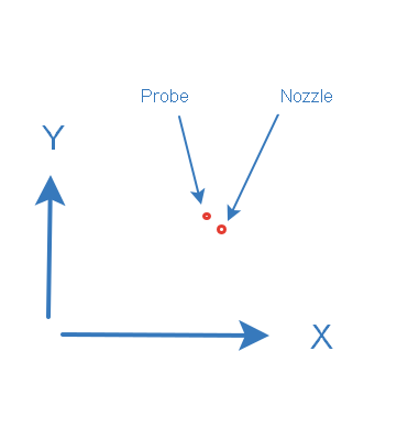
your probe is to the right and behind the nozzle?
-
No. Probe is to the left and behind the nozzle. (Homing point on the left and front of the printer)
-
-
G31 P25 X27 Y-4 Z1.78 ; set probe height
your configuration says to the right and infront.
-
Ahh. Thanks! I will try now G31 P25 X-27 Y4 Z1.78 ; set probe height
-
Thanks for the tip! It really helped and now even with a probing step 50mm everything is fine!
-
glad its sorted. can you mark the thread as solved?
-
No, I still can’t figure it out.
Yes, the table is really ragged. But what does it matter?
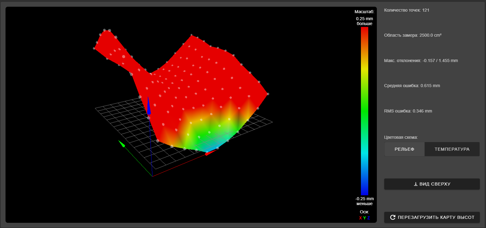
RepRapFirmware height map file v2 generated at 2019-11-01 19:53, min error -0.157, max error 1.455, mean 0.615, deviation 0.346
xmin,xmax,ymin,ymax,radius,xspacing,yspacing,xnum,ynum
450.00,950.00,120.00,620.00,-1.00,50.00,50.00,11,11
  0.311,  0.163,  0.054, -0.041, -0.157, -0.153, -0.096, -0.007,  0.135,  0.285,  0.481
  0.538,  0.388,  0.246,  0.109,  0.003,  0.019,  0.069,  0.128,  0.265,  0.423,  0.625
  0.749,  0.588,  0.436,  0.264,  0.150,  0.147,  0.190,  0.264,  0.378,  0.504,  0.729
  0.988,  0.760,  0.609,  0.402,  0.303,  0.273,  0.265,  0.342,  0.466,  0.623,  0.821
  1.175,  0.966,  0.754,  0.567,  0.426,  0.389,  0.408,  0.439,  0.588,  0.733,  0.941
  1.392,  1.108,  0.892,  0.671,  0.523,  0.485,  0.468,  0.534,  0.659,  0.795,  0.985
  1.455,  1.171,  0.922,  0.739,  0.558,  0.514,  0.530,  0.602,  0.694,  0.816,  1.001
  1.438,  1.153,  0.944,  0.734,  0.558,  0.535,  0.558,  0.613,  0.688,  0.823,  1.000
  1.352,  1.097,  0.919,  0.732,  0.618,  0.532,  0.606,  0.649,  0.783,  0.928,  1.065
  1.211,  1.003,  0.823,  0.625,  0.536,  0.518,  0.587,  0.633,  0.756,  0.955,  1.108
  1.086,  0.891,  0.752,  0.581,  0.519,  0.491,  0.552,  0.658,  0.813,  0.972,  1.133
In the photo there is a fragment of a part that covers several calibration points. Why is this place not aligned?
Is it possible that the firmware has restrictions on the height of the table when adjusting?
I changed the calibration settings
M208 X0 Y-35 Z0 S1 ; set axis minima M208 X1380 Y1210 Z1500; Set axis maxima M557 X450:950 Y120:620 S50 M376 H6 -
it means that your bed is very uneven. as you have 0.2 differences between probing point (an entire layer) there is only so much that the mesh can compensate for. you will need a lot smaller spacing i would imagine.
can you post a picture of the mesh.
-
Do you want to say that mesh calibration cannot compensate for more than 0.2mm?
-
that looks absolutly terrible.
i am saying that if you have 0.2 between two points the area in between is calculated, so there could be deviations to the real values.
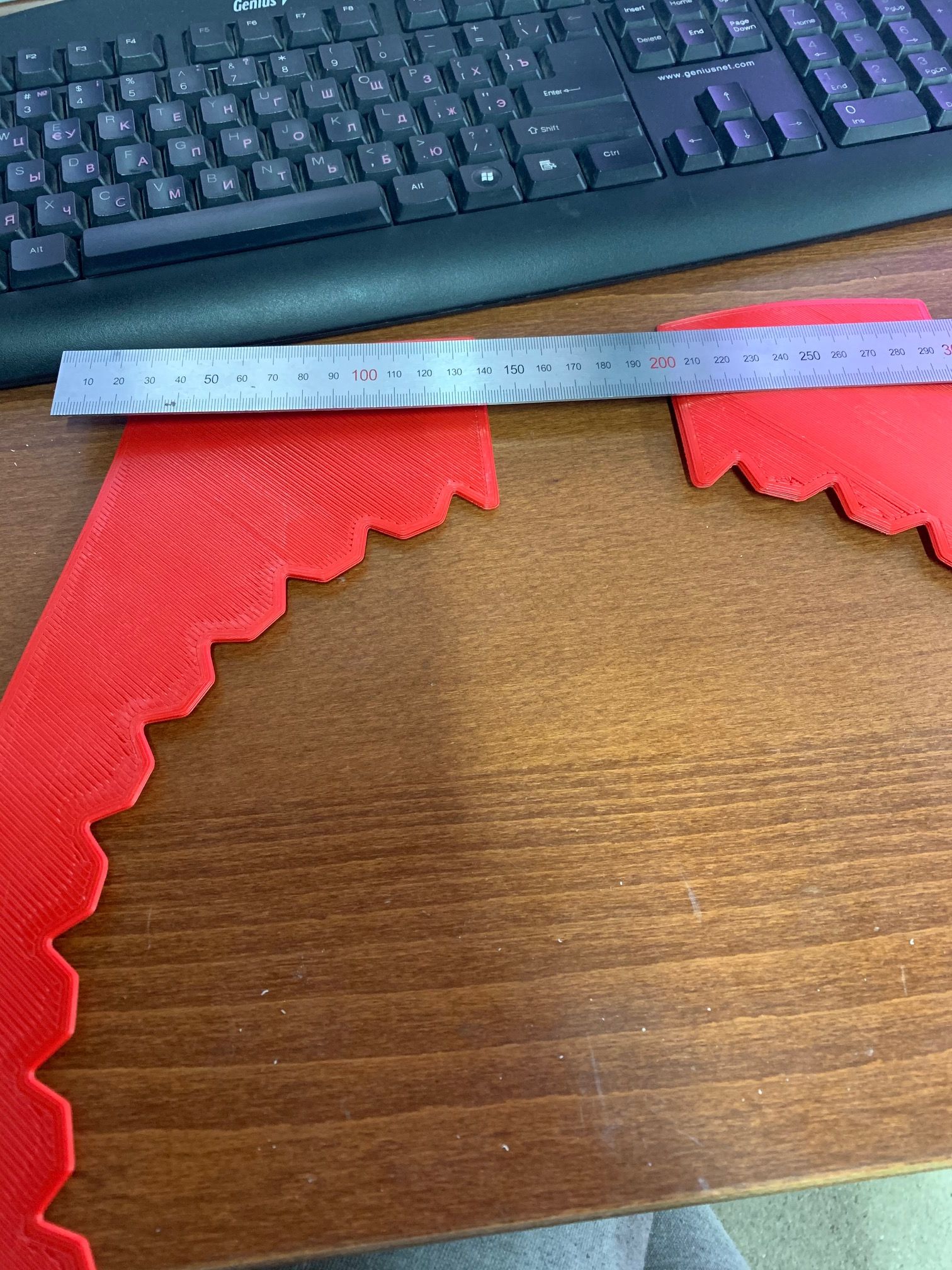
with a bed as uneven as that it is very likely that that is the case.however looking at our printer setup, it could also be a mechanical issue with your x gantry. because of the length it could be sagging and produces this result.
-
All axes are calibrated and checked. Dimensions of printed part + - 0.2 mm
OK. The table is very uneven. But for calibration, what does it matter?
Why doesn't calibration work in this range?
Is there a limitation?
-
@Dep said in Mesh calibration not working or what am I doing wrong?:
All axes are calibrated and checked. Dimensions of printed part + - 0.2 mm
axis sagging has nothing to do with dimension.
your x axis and y axis are over a meter long. they could bend under their own weight of the beam is not rigid enough.
that would lead to an image you are seeing, where the sides are higher and the middle is low. i.e the weight in the middle is causing more deflection that on the sides.