Help with a few configuration issues.
-
-
- Cannot get layer fans to show up in DWC and also cannot get them to come on during a print
-
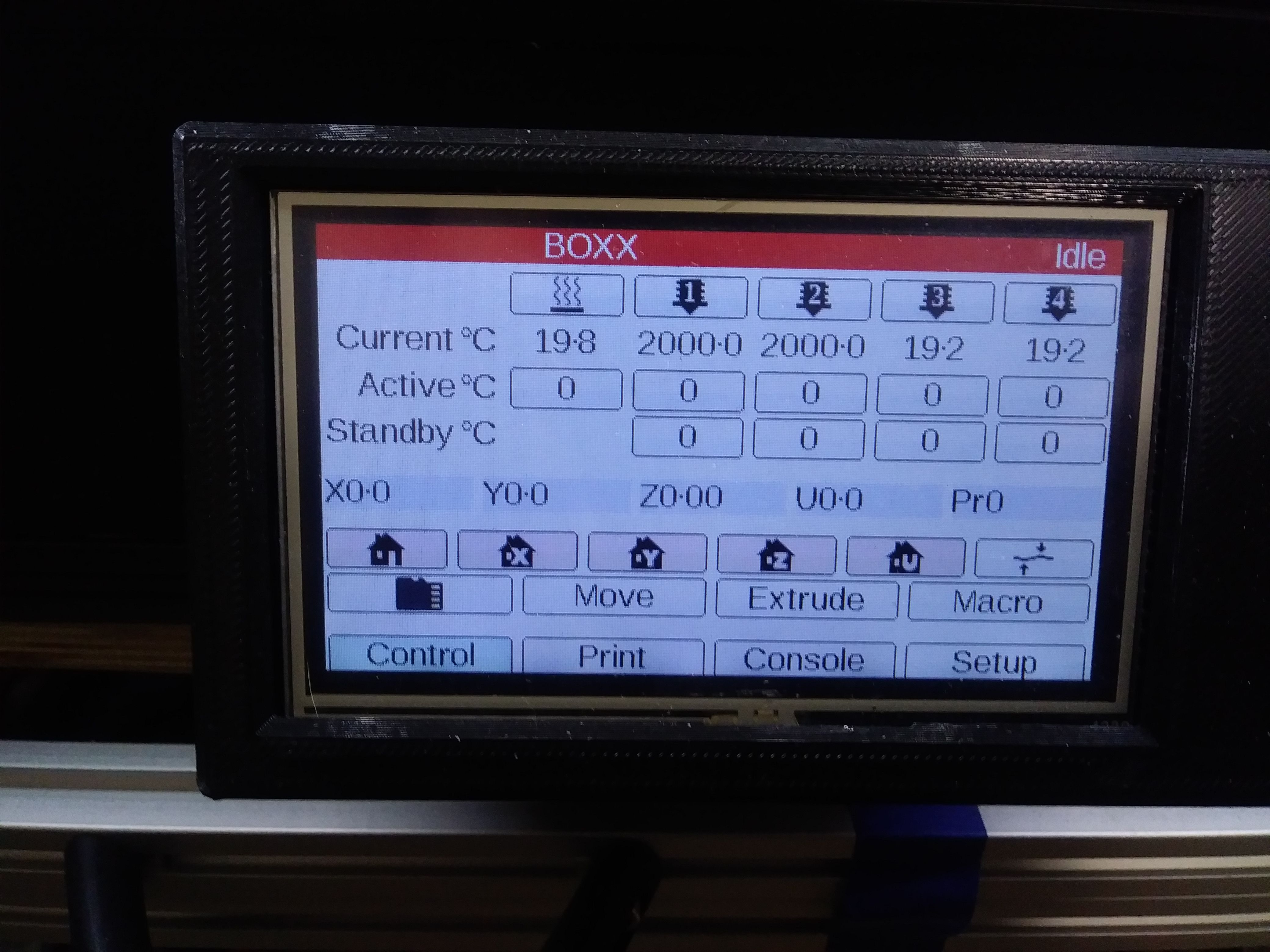
- I have my two extruders set up on my Duex5 on heaters 3 & 4 using drives 5 & 6. They show up fine in the DWC but not on my panel Due 4.3. I have updated the panel due firmware to the latest but this is how they show up.

As you can see I cannot get them to show up as 1 & 2 and instead show up as 3 & 4. I am not using any heaters on my Duet Wifi, only the Duex5
- I have my two extruders set up on my Duex5 on heaters 3 & 4 using drives 5 & 6. They show up fine in the DWC but not on my panel Due 4.3. I have updated the panel due firmware to the latest but this is how they show up.
INFO:
Board: Duet WiFi 1.0 or 1.01 + DueX5
Firmware: RepRapFirmware for Duet 2 WiFi/Ethernet 2.04 (2019-11-01b1)
Duet WiFi Server Version: 1.23
Duet Web Control 2.0.4Here is my CONFIG.g
; Configuration file for Duet WiFi (firmware version 1.21)
; executed by the firmware on start-up
;General preferences*******************************************************************
G90 ; Send absolute coordinates...
M83 ; ...but relative extruder moves
M669 K1 ; Select CoreXY mode;Axis Limit*******************************************************************
M208 X0:355 Y0:355 Z0:400 ; Set axis min/max
;M208 U0:180 ; Set axis min/max;Endstop Settings*******************************************************************
M574 Z1 S2 ; Set endstops controlled by probe
M574 X1 Y1 S1 ; Set active high endstops
;M574 U1 S1 ; Set homing switch configuration for toolchange lock. Both switches should be wired NC and in series.;Z-Probe*******************************************************************
M307 H7 A-1 C-1 D-1 ; Disable heater on PWM channel for BLTouch
M558 P9 F100 H5 R0.2 T6000 B0 ; Set Z probe type to BLTouch and the dive height + speeds
G31 P25 X-3 Y-39.3 Z0.4 ; Set Z probe trigger value, offset and trigger height
M557 X15:350 Y20:350 S2 ; Define mesh grid;Drives*******************************************************************
M584 X0 Y1 Z2:3 E5:6 ; Drive mapping
;M584 U4 ; Drive mappingM569 P0 S0 ; X Drive 0 goes forwards
M569 P1 S1 ; Y Drive 1 goes backwardsM569 P2 S1 ; Z1 Drive 2 goes backwards
M569 P3 S1 ; Z2 Drive 3 goes backwards;M569 P4 S1 ; U Drive 4 goes backwards
M569 P5 S0 ; E0 Drive 5 goes forwards
M569 P6 S0 ; E1 Drive 6 goes forwards;M569 P7 S0 ; NOT USED
;M569 P8 S0 ; NOT USED
;M569 P9 S0 ; NOT USEDM350 X16 Y16 Z16 E16:16 U16 I1 ; Configure microstepping with interpolation
M92 X66 Y66 Z1600 E443.62:443.62 U100 ; Set steps per mmM566 X200 Y200 Z300 E1000:1000 U100 ; Set maximum instantaneous speed changes (Jerk) (mm/min)
M203 X30000 Y30000 Z400 E4000:4000 U5000 ; Set maximum speeds (mm/min)
M201 X600 Y600 Z20 E1000:1000 U800 ; Set accelerations (mm/s^2)M906 X1200 Y1200 Z1300 E300:600 U1500 I30 ; Set motor currents (mA) and motor idle factor in percent
M84 S30 ; Set idle timeout;Heaters*******************************************************************
M305 S"BED" P0 T100000 B4138 C0 ; Set thermistor
M143 H0 S225 ; Set temperature limit for heater 0 to 225CM305 S"T0" P3 R4700 T100000 B4388 ;Set thermistor
M143 H3 S300 ; Set temperature limit for heater 3 to 300CM305 S"T1" P4 R4700 T100000 B4388 ; Set thermistor
M143 H4 S300 ; Set temperature limit for heater 4 to 300C;Tools*******************************************************************
M563 S"T0" P0 D0 H3 ; Define tool 0
G10 P0 X0 Y0 Z0 ; Reset tool 0 axis offsets
G10 P0 R0 S0 ; Reset initial tool 0 active and standby temperatures to 0CM563 S"T1" P1 D1 H4 ; Define tool 1
G10 P1 X0 Y0 Z0 ; Reset tool 1 axis offsets
G10 P1 R0 S0 ; Reset initial tool 1 active and standby temperatures to 0C;tool offsets
G10 P0 X9 Y39 Z0 ; T0
G10 P1 X9 Y39 Z0 ; T1
;G10 P2 X-9 Y39 Z-5 ; T2
;G10 P3 X-9 Y39 Z-5 ; T3;Fans*******************************************************************
;M106 P0 S0 I0 F500 H-1 ; UNUSED
M106 C"T0 FAN" P3 S255 I0 F500 H3 T70 ; T0 HE
M106 C"T0 LAY FAN" P4 S0 I0 F500 H-1 ; T0 PCF
M106 C"T1 FAN" P5 S0 I0 F500 H4 T70 ; T1 HE
M106 C"T1 LAY FAN" P6 S0 I0 F600 H-1 ; T1 PCF
;M106 P7 S0 H3 T70 ; T2 HE
;M106 P8 S0 ; T2 PCF -