Connecting the brake system stepper motor
-
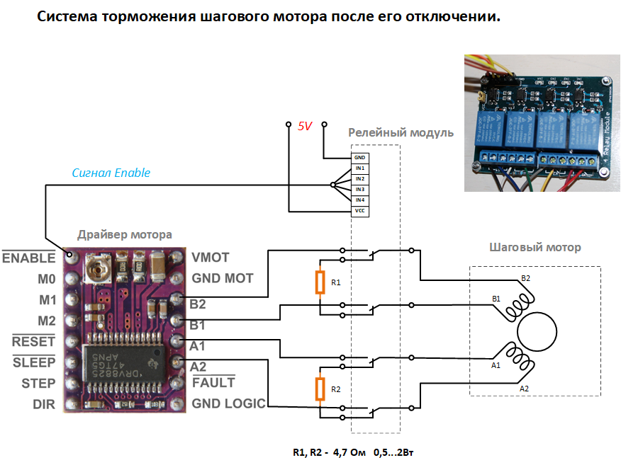
Good afternoon. I want to put Duet 2 wi fi, but there was a question. I have a belt in place of the screw on the z axis and used a relay for braking. Diagram:
How can I connect the relay to the TMC2660 drivers? Thanks for the answers. -
@shadrincev Pin 28 on the expansion header is "ENN", the stepper driver enable pin. Others have used this to enable shorting of stepper coils for braking Z axis. See my post here https://forum.duet3d.com/post/122014
See wiring diagram here for pin 28 location:
https://d17kynu4zpq5hy.cloudfront.net/igi/duet3d/vqBUAZPsxMC5tRgt.hugeIan
-
Thank you, but according to the scheme pin ENN is common to all drivers and when you turn on the control wire of the relay, pin 28, the relay is turned on, but the motors are not active at this time, which leads to a sharp lowering of the table. Maybe you can assign a separate pin, so that when the z-axis driver is activated, it turns on the relay, and when it is inactive, it turns off?
-
Driver enable/disable of TMC2660 drivers is handled over SPI. That is why they don't have separate enable pins.
Using a relay that operates at the same time as the enable pin is risky, because you will be relying on the motor current dropping to zero before the relay actually disconnects. It would be better to switch the relay on a little before the enable command is sent, and turn it off a little after the drive is disabled. Or you could mitigate the risk by using 8 Schottky diodes to clamp all 4 motor connections to VMOT and ground.
Duet WiFi hardware designer and firmware engineer
Please do not ask me for Duet support via PM or email, use the forum
http://www.escher3d.com, https://miscsolutions.wordpress.com -
It would be better to switch the relay on a little before the enable command is sent, and turn it off a little after the drive is disabled.I'm just getting to know the RRF. So I do not know how it can be implemented. Please tell me how to do it?
-
This post is deleted! -
As I understand it, there is no solution at the moment?
-
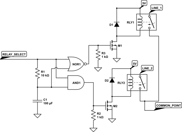
Maybe if you could find a relay that has make-before-break contacts to avoid disconnecting the driver output at all when enabling the brake.
-
@bearer I understand you.

But, then again the same question, how to control the PWM signal? I understand that you can release one of the unused heaters, as with BLTOUCH, but what to write in the configuration so that it gives a logical 1 when you start using the driver, and a logical 0 when you turn off, or set. -
In MARLIN found such a function, and in RRF there is something similar with FAN?
* The fan will turn on automatically whenever any stepper is enabled
* and turn off after a set period after all steppers are turned off.
#define USE_CONTROLLER_FAN
#if ENABLED(USE_CONTROLLER_FAN)
#define CONTROLLER_FAN_PIN 6 // Set a custom pin for the controller fan
#define CONTROLLERFAN_SECS 1 // Duration in seconds for the fan to run after all motors are disabled
#define CONTROLLERFAN_SPEED 255 // 255 == full speed
#endif
I think it will suit me.
-
Personally, I'd take an offboard hardware approach. Have an Arduino or ESP32 or ESP8266 monitor SPI, looking for the enable/disable going to that one axis. Click the relay some number of milliseconds after you see a disable. Release it on enable.
-
Hmm, there was already an attempt to implement brake control. Stepper brake feature #220
Only who will explain, entered it in the firmware and how to use it, configure? -
@shadrincev said in Connecting the brake system stepper motor:
I have a belt in place of the screw
same here, I assume you want to allow Z bed to "slowly drop" instead of a "thump crash" after the enable for Z is off
") ... that printer is still on smoothieware and there the enable does not "auto" go on/off you have to manually do it with M17/M18/M84 so I have a "stop script" that moves the head where I want it waits a second and than M18 that kills the enable, energizes the relay on z and allows for slow drop of the bed. now in my setup R1 and R2 is 0 I directly short the nema17 with relay, had no issues with it for almost a decade
... that printer is still on smoothieware and there the enable does not "auto" go on/off you have to manually do it with M17/M18/M84 so I have a "stop script" that moves the head where I want it waits a second and than M18 that kills the enable, energizes the relay on z and allows for slow drop of the bed. now in my setup R1 and R2 is 0 I directly short the nema17 with relay, had no issues with it for almost a decadenow, I wanted to do the same with duet3 on ender5 as original screw allow bed to drop like stone but I gave up and replaced the Z threaded rod to a different one that holds it in place on it's own but on the expansion port there is ENN output that you can use but I'm not sure about timing, have not measured it myself, and don't know how often the ENN is switched on the duet itself, is it only controlled with M17/18 or there are events where it's switched on/off on it's own.
-
@dc42 said in Connecting the brake system stepper motor:
8 Schottky diodes to clamp
I actually wanted to ask, but controled myself not to
 .... why is noone doing this?!?!?! duet*, smoothieboard, all those gen*, skr*, rambo* ... nowhere you can see the "required" 8 diodes on the output?! while for e.g. even the low power cnc drivers from china have those?! (the lowest price ones go with 4 diodes per motor, but none go with no diodes) .. diodes are not that expensive, not sure why is that a problem? I seen PRC is now selling the "underboard" for pololu style modules with 8 diodes, I have my external 8 diode boards I designed decade ago that I use (actually should find the gerbers and shoot to PRC for more pcb's I'm out of them and toolchanger is arriving on monday ) /... weeird choice that noone is adding those diodes and everyone knows about them ?!?!?! especially, if you remember bitsfrombytes, they had some weird reseting problem and then a guy was "giving away" upgrade for their electronics that was solving the issue, it had a big board with 32x1n5819 for the output and a small board with 2x1n5819 and 4 tantalum caps on the analog input .. that solved all the reseting issues with bitsfrombytes board (actually good board based on pic32mx, 32bit mips core 10 years ago while everyone was using atmega644p (sanguino) for running printers ... shitty firmware but great board) ... I expected after that leason everyone will add the input and output protection diodes and caps ?! but for some reason..
 -
Because such diodes would have a negative effect on 'normally' operating driver<>motor relationships, changing the waveforms, and 99.9% of installations don't need them.
But mostly the first part.
-
@Danal
Diodes have nothing to do with it, I even gave a link to the implementation, and explain how to do it no one can or does not want to, although this question has been raised since 2016.... I'm sorry, but terrible support for the project.