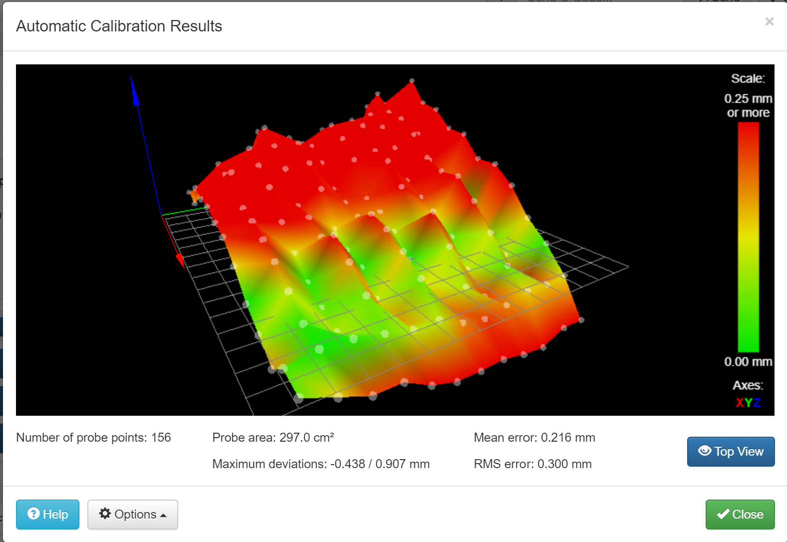
BLTouch create weird bumps in mesh
-
Hey, so I've just swapped to the BLTouch and I have some issues after setting it up
My mesh looks like this

and I don't whyhere is my config.g:
; General preferences
G90                                                                            ; Send absolute coordinates...
M83                                                                            ; ...but relative extruder moves

; Drives
M569 P0 S0                                                                     ; Physical drive 0 goes forwards
M569 P1 S0                                                                     ; Physical drive 1 goes forwards
M569 P2 S1                                                                     ; Physical drive 2 goes backwards
M569 P3 S0                                                                     ; Physical drive 3 goes forwards
M350 X16 Y16 Z16 E16 I1                                                        ; Configure microstepping with interpolation
M92 X100.00 Y100.00 Z400.00 E90.00                                             ; Set steps per mm
M566 X600.00 Y600.00 Z18.00 E300.00                                            ; Set maximum instantaneous speed changes (mm/min)
M203 X6000.00 Y6000.00 Z180.00 E6000.00                                        ; Set maximum speeds (mm/min)
M201 X1500.00 Y1500.00 Z100.00 E10000.00                                       ; Set accelerations (mm/s^2)
M906 X500.00 Y500.00 Z500.00 E800.00 I30                                       ; Set motor currents (mA) and motor idle factor in per cent
M84 S30                                                                        ; Set idle timeout

; Axis Limits
M208 X-48.90 Y-3.00 Z0 S1                                                      ; Set axis minima
M208 X220 Y220 Z240 S0                                                         ; Set axis maxima

; Endstops
M574 X1 Y1 S0                                                                  ; Set active low and disabled endstops

; Z-Probe
M307 H3 A-1 C-1 D-1							       ; Set Z probe trigger value, offset and trigger height
M558 P9 H5 F100 T2000
G31 X-21 Y-54 Z1.023 P25

; Heaters
M307 H0 B0 S1                                                                  ; Disable bang-bang mode for the bed heater and set PWM limit
M305 P0 T100000 B4725 C7.060000e-8 R4700                                       ; Set thermistor + ADC parameters for heater 0
M143 H0 S80                                                                    ; Set temperature limit for heater 0 to 80C
M307 H0 A187.0, C617.0, D8.1 S1                                                ; PID Bed - 5 way Diamond
M305 P1 T100000 B3950 C7.060000e-8 R4700                                       ; Set thermistor + ADC parameters for heater 1
M143 H1 S250                                                                   ; Set temperature limit for heater 1 to 250C
M307 A599.9 C121.3 D4.5 S1                                                     ; PID Heater 5 way Diamond


; Fans
M106 P0 S0.6 I0 H1 T120 X0.7                        ; set fan 0 value, PWM signal inversion and frequency. Thermostatic control is turned on
M106 P1 S1.0 I0 H1 T45                         ; set fan 1 value, PWM signal inversion and frequency. Thermostatic control is turned on

; Tools
M563 P0 H1 D0                                                                  ; Define tool 0
G10 P0 X0 Y0 Z0                                                                ; Set tool 0 axis offsets
G10 P0 R0 S0                                                                   ; Set initial tool 0 active and standby temperatures to 0C

; Automatic power saving
M911 S22 R23 P"M913 X0 Y0 G91 M83 G1 Z3 E-5 F1000"                             ; Set voltage thresholds and actions to run on power loss

; Custom settings are not configured

; Miscellaneous
T0                                                                             ; Select first tool
Here is my bed.g:
M401
G29  ; probe the bed and enable compensation
G29 S1
Could it be a physical problem? I printed my own mount
-
I think your bed is rocking back and forth, so that on the left-hand scans the height has one value, and on the right-hand scans the height has another. This could be because the x belt is pulling off-center on the carriage, or the carriage is just loose.
-
I agree with @mendenmh
You can see the back and forth pattern. It starts at the 0,0 corner with the arrows, moves to the right, then comes back towards the left, etc etc. The probe is tilting depending on which direction it was last moved, in other words, backlash.
Can you post a photo of your printer and a detail shot of the print head with bltouch mount?
-
@CookieHunter said in BLTouch create weird bumps in mesh:
G31 X-21 Y-54 Z1.023 P25
I’d say it was because of the large Y offset of the probe and small rocking of the X carriage is being amplified by the offset. Try to mount the probe closer to the nozzle, preferably in line in X, so the Y offset is 0.
Ian