Logic Level shifter for 12864 display on Duet 2 Wifi
-
@bearer said in Logic Level shifter for 12864 display on Duet 2 Wifi:
And if the lcd has a proper spi interface it should ignore mosi/sck when cs isn't asserted so idk.
That's what one would expect; however the V4.0 ST7920 datasheet says on page 29:
When chip select (CS) is low, ST7920 serial clock counter and serial data will be reset. Serial transfer counter is set
to the first bit and data register is cleared. After CS is “L”, any further change on SID or SCLK is not allowed. It is
recommended to keep SCLK at “L” and SID at the last status before set CS to “L”. For a minimal system with only
one ST7920 and one MPU, only SCLK and SID pins are necessary. CS pin should pull to high.That's why we gate SCLK with CS on the Maestro.
-
@dc42 said in Logic Level shifter for 12864 display on Duet 2 Wifi:
That's why we gate SCLK with CS on the Maestro.
Thanks for confirming! Suspected as much from the design, 2 for 1 with the and gate, probably timing (or Gremlins) preventing the txs0108 module achieving the same thing.
Will poke it some more another day or perhaps sneak a 74hct08 in on the next part order.
-
@bearer said in Logic Level shifter for 12864 display on Duet 2 Wifi:
probably timing (or Gremlins) preventing the txs0108 module achieving the same thing.
not 100% sure where the gremlings are/were but( <- dodgy USB cable and unstable 5v)
It works! Duet2Wifi + TXS0108 + RepRapDiscount Smart Controller (or geeetech clone with the headers corrected in any case). Confirms patch against 2.05 and schematic at least.
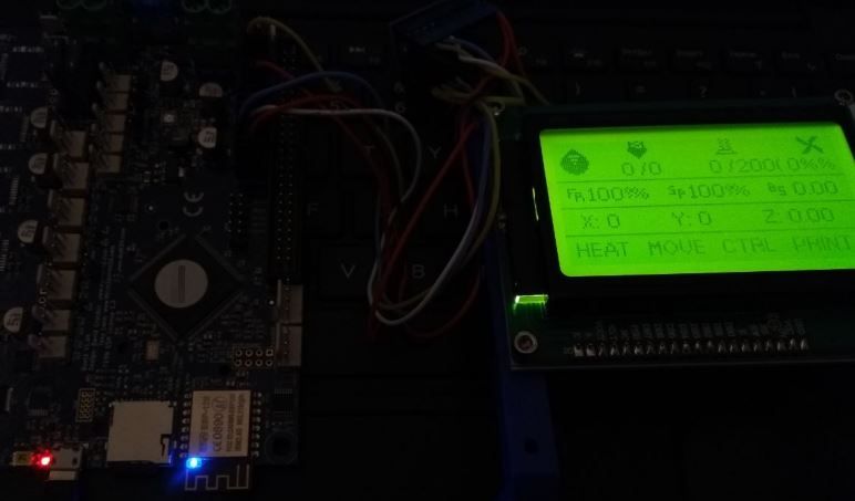
M918
12864 display is configured, pulses-per-click is 2
M115
FIRMWARE_NAME: RepRapFirmware for Duet 2 WiFi/Ethernet FIRMWARE_VERSION: 2.05.x LCD ELECTRONICS: Duet WiFi 1.02 or later FIRMWARE_DATE: 2020-04-16b4
forecast changed its mind no sunshine today >.<
edit: i would propose swapping lcd_cs to from PortDPin(21) / lcdconn.10 to PortAPin(7) / sdconn.7 as it would enable a single 10 way ribbon cable to function as just a display + sd reader (but no buttons/beep). Or maybe utxd0, urxd0 and spi0_cs could be used if the reader isn't present or needed.
(edit2: yes, i'm aware the duet is missing some parts)
-
@dc42 are there any conventions or limitations to
# define MAIN_VERSION "2.05"
# define DATE "2020-04-14b3"
i see 3.01-RC7 gets a conditional
# define VERSION_SUFFIX " (CAN0)"is that the way to go for various mischief? (i.e.
mlx90614too long a string to add?) -
Yes I suggest you use a version suffix. I agree that mlx90614 is rather long. It's also obscure, at least to me. What does it mean?
-
@dc42 said in Logic Level shifter for 12864 display on Duet 2 Wifi:
What does it mean?
unless i got it wrong its one of the non-contact spi temp sensors left over from an EV charger build. might find its way into a printer if this pandemic thing drags out..
but its aslo about the length of a short commit id so was wondering if there is a hard limit that i didn't see in my limited search. i don't expect to share any binaries but figure clearly tagging them in case of issues would be good.
-
@bearer said in Logic Level shifter for 12864 display on Duet 2 Wifi:
Edit: WIP RRF3 patch
huh, must have missed it earlier:/
..bin/ld: Duet2CombinedFirmware.elf section `.ARM.exidx' will not fit in region `rom'
..bin/ld: region `rom' overflowed by 4900 bytes
oh well, RRF2 for now.
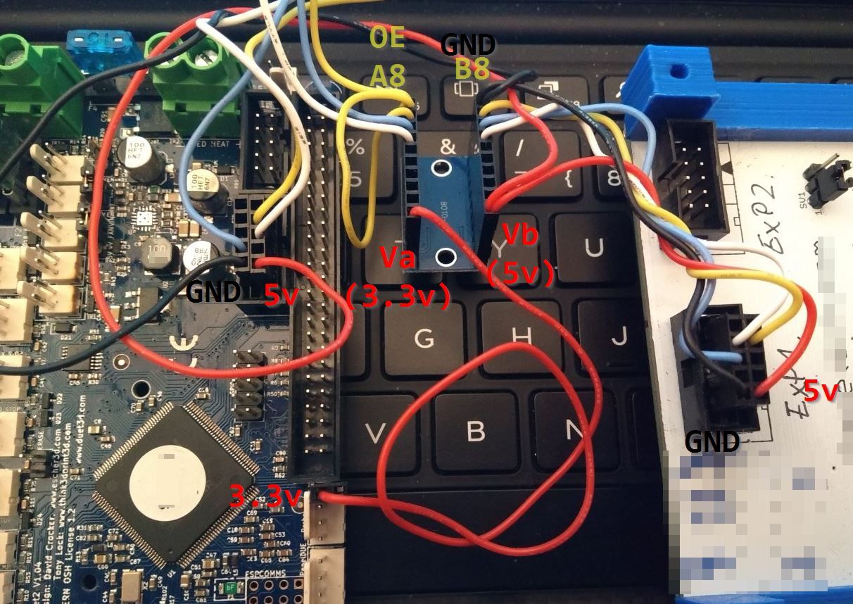
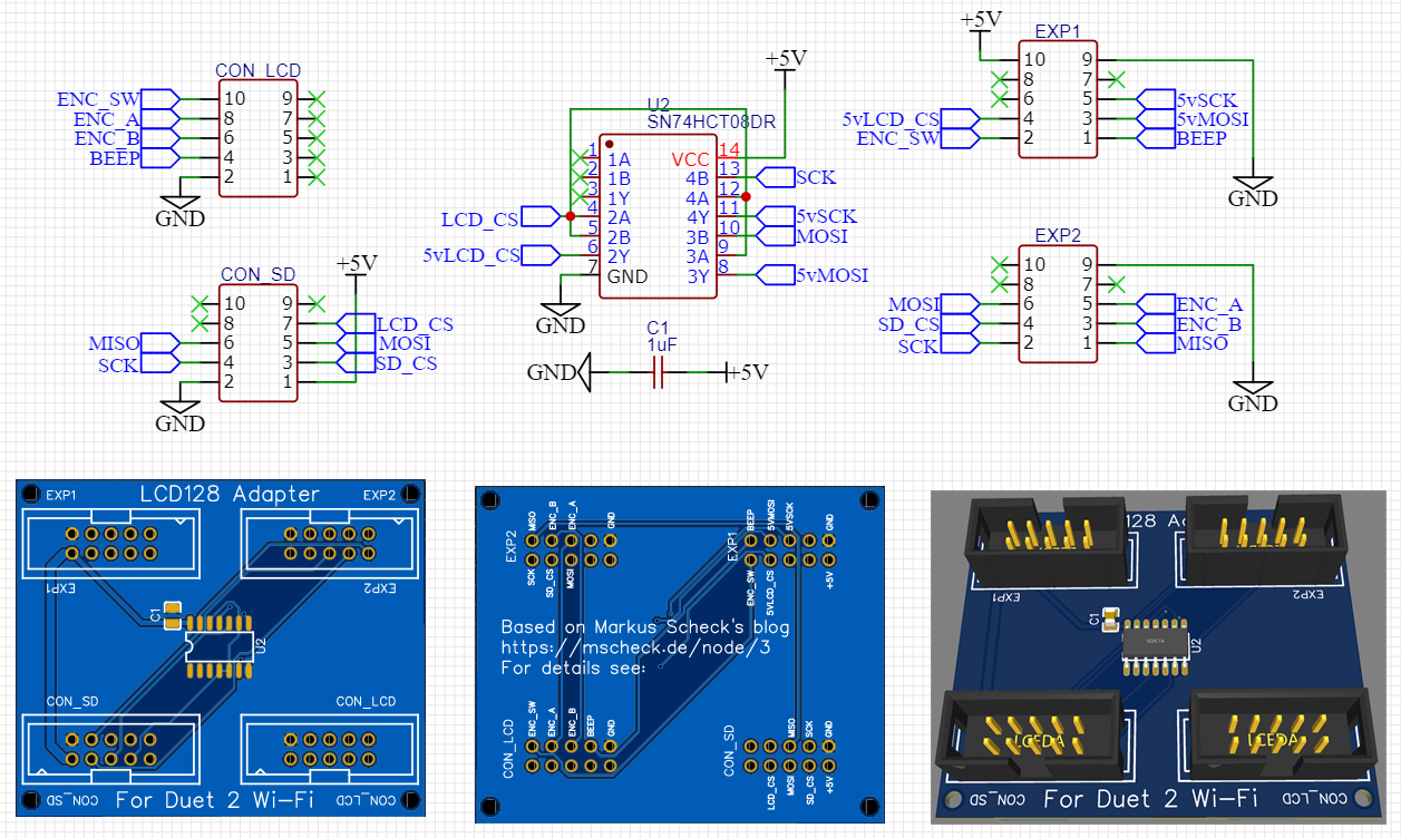
edit @ oliof: clearer picture of the wiring with some labels, do note I swapped two pins from the blogpost
diff --git a/src/DuetNG/Pins_DuetNG.h b/src/DuetNG/Pins_DuetNG.h
index a9c30059..620d14ef 100644
--- a/src/DuetNG/Pins_DuetNG.h
+++ b/src/DuetNG/Pins_DuetNG.h
@@ -28,7 +28,7 @@ constexpr size_t NumFirmwareUpdateModules = 4;                // 3 modules, plus one for manua
 #define SUPPORT_IOBITS                 1                                       // set to support P parameter in G0/G1 commands
 #define SUPPORT_DHT_SENSOR             1                                       // set nonzero to support DHT temperature/humidity sensors
 #define SUPPORT_WORKPLACE_COORDINATES  1                                       // set nonzero to support G10 L2 and G53..59
-#define SUPPORT_12864_LCD              0                                       // set nonzero to support 12864 LCD and rotary encoder
+#define SUPPORT_12864_LCD              1                                       // set nonzero to support 12864 LCD and rotary encoder
 #define SUPPORT_OBJECT_MODEL           1
 #define SUPPORT_FTP                    1
 #define SUPPORT_TELNET                 1
@@ -37,11 +37,11 @@ constexpr size_t NumFirmwareUpdateModules = 4;              // 3 modules, plus one for manua

 // The physical capabilities of the machine

-constexpr size_t NumDirectDrivers = 12;                                // The maximum number of drives supported directly by the electronics
+constexpr size_t NumDirectDrivers = 11;                                // The maximum number of drives supported directly by the electronics
 constexpr size_t MaxTotalDrivers = NumDirectDrivers;                   // The maximum number of drives including CAN expansion
 constexpr size_t MaxSmartDrivers = 10;                                 // The maximum number of smart drivers

-constexpr size_t NumEndstops = 12;                                     // The number of inputs we have for endstops, filament sensors etc.
+constexpr size_t NumEndstops = 11;                                     // The number of inputs we have for endstops, filament sensors etc.
 constexpr size_t NumHeaters = 8;                                       // The number of heaters in the machine
 constexpr size_t NumExtraHeaterProtections = 8;                        // The number of extra heater protection instances
 constexpr size_t NumThermistorInputs = 8;
@@ -72,9 +72,29 @@ constexpr Pin AdditionalIoExpansionStart = 220;              // Pin numbers 220-235 are on t

 // DRIVES
 constexpr Pin GlobalTmc2660EnablePin = 38;                     // The pin that drives ENN of all TMC2660 drivers on production boards (on pre-production boards they are grounded)
-constexpr Pin ENABLE_PINS[NumDirectDrivers] = { 78, 41, 42, 49, 57, 87, 88, 89, 90, 31, 82, 60 };
-constexpr Pin STEP_PINS[NumDirectDrivers] = { 70, 71, 72, 69, 68, 66, 65, 64, 67, 91, 84, 85 };
-constexpr Pin DIRECTION_PINS[NumDirectDrivers] = { 75, 76, 77, 01, 73, 92, 86, 80, 81, 32, 83, 25 };
+constexpr Pin ENABLE_PINS[NumDirectDrivers] = { 78, 41, 42, 49, 57, 87, 88, 89, 90, 31, 82};
+constexpr Pin STEP_PINS[NumDirectDrivers] = { 70, 71, 72, 69, 68, 66, 65, 64, 67, 91, 84};
+constexpr Pin DIRECTION_PINS[NumDirectDrivers] = { 75, 76, 77, 01, 73, 92, 86, 80, 81, 32, 83};
+
+// 12864 LCD
+// The ST7920 datasheet specifies minimum clock cycle time 400ns @ Vdd=4.5V, min. clock width 200ns high and 20ns low.
+// This assumes that the Vih specification is met, which is 0.7 * Vcc = 3.5V @ Vcc=5V
+// The Duet Maestro level shifts all 3 LCD signals to 5V, so we meet the Vih specification and can reliably run at 2MHz.
+// For other electronics, there are reports that operation with 3.3V LCD signals may work if you reduce the clock frequency.
+// ST7920 doesn't allow SCK/MISO signals when CS is not asserted, therefore the AND gate on the Maestro
+constexpr uint32_t LcdSpiClockFrequency = 2000000;     // 2.0MHz            -- Top View --
+constexpr Pin LcdCSPin = 7;      //connsd.7   --> gate -> exp1.4            |            |
+constexpr Pin LcdBeepPin = 60;   //connlcd.4           -> exp1.1            |  10*  *9   |
+constexpr Pin EncoderPinA = 85;  //connlcd.8           -> exp2.5            |            |
+constexpr Pin EncoderPinB = 25;  //connlcd.6           -> exp2.3            |   8*  *7  _|
+constexpr Pin EncoderPinSw = 8;  //connlcd.10           -> exp1.2           |          |
+                                 //adittional spi wiring:                   |   6*  *5 |
+                                 //connsd.6            <- exp2.1 (SD MISO)  |          |_
+                                 //connsd.5   --> gate -> exp1.3 (LCD MOSI) |   4*  *3   |
+                                 //            `->     -> exp2.6 (SD MOSI)  |            |
+                                 //connsd.4   --> gate -> exp1.5 (LCD SCK)  |   2*  #1   |
+                                 //            `->     -> exp2.2 (SD SCK)   |            |
+                                 //connsd.3            -> exp2.4 (SD CS)    --------------

 // Pin assignments etc. using USART1 in SPI mode
 Usart * const USART_TMC2660 = USART1;
@@ -92,7 +112,7 @@ constexpr Pin DueX_INT = 17;                                         // DueX interrupt pin = PA17 (was E6_STOP)
 // Endstops
 // RepRapFirmware only has a single endstop per axis.
 // Gcode defines if it is a max ("high end") or min ("low end") endstop and sets if it is active HIGH or LOW.
-constexpr Pin END_STOP_PINS[NumEndstops] = { 46, 02, 93, 74, 48, 96, 97, 98, 99, 17, 39, 8 };
+constexpr Pin END_STOP_PINS[NumEndstops] = { 46, 02, 93, 74, 48, 96, 97, 98, 99, 17, 39};
 constexpr Pin DUEX_END_STOP_PINS[5] = { 200, 203, 202, 201, 213 };                             // these replace endstops 5-9 if a DueX is present

 // HEATERS
diff --git a/src/Version.h b/src/Version.h
index ac15bf0a..81082397 100644
--- a/src/Version.h
+++ b/src/Version.h
@@ -11,7 +11,7 @@

 #ifndef VERSION
 #ifdef RTOS
-# define MAIN_VERSION  "2.05.1"
+# define MAIN_VERSION  "2.05.1+LCD"
 #else
 # define MAIN_VERSION  "1.26.1"
 #endif
@@ -20,7 +20,7 @@
 #endif

 #ifndef DATE
-# define DATE "2020-02-09b1"
+# define DATE "2020-04-16b8"
 #endif

 #define AUTHORS "reprappro, dc42, chrishamm, t3p3, dnewman, printm3d"
(apply patch with
git apply --ignore-whitespace lcd12864.patchas whitespace was tweaked for display)
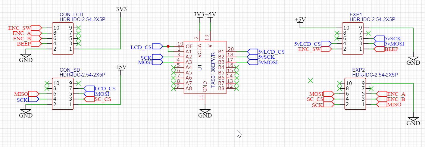
And schematic; i only wired up the blue lines on the drawing.
-
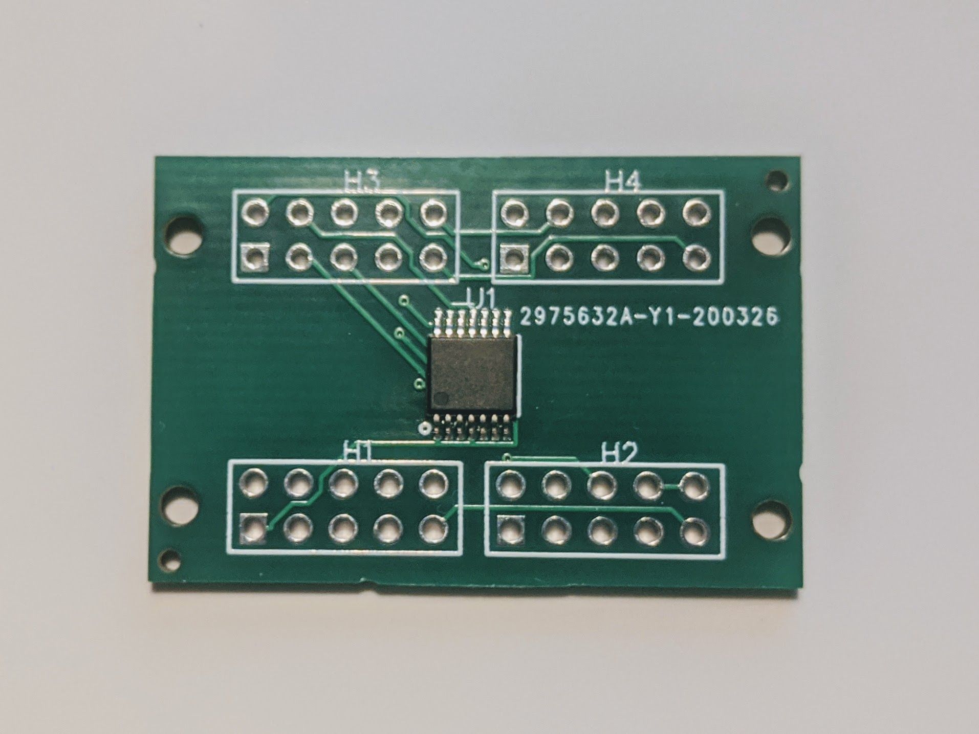
Got a delivery of ten boards with 74HCT08 on them just now. Tomorrow I'll need to solder on a bunch of headers ...
-
@oliof said in Logic Level shifter for 12864 display on Duet 2 Wifi:
Got a delivery of ten boards with 74HCT08 on them just now.
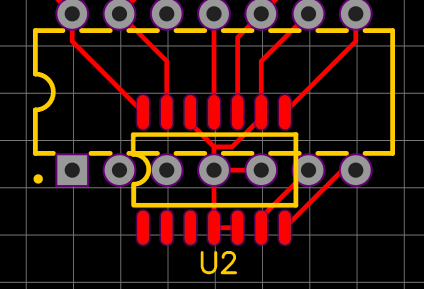
wow thats fast! if thats from the original schematic in the blog post beware pin1 (the square pin) isn't really pin1 on all of those headers; read the description of how to orient the notches on the headers/idc's. (eyeballing it i'd say its H1 and H2 that are reversed, but do check the description)
-
Indeed, 3 weeks turnaround isn't too bad (-:
It's the unchanged schematics and I will be careful!
In my pursuit for a small board to hide alon a cable length I may have left too little clearance for the headers.
A revision is likely inevitable, and then I'd go for your fixed layout if it's finalized by then.
-
@oliof said in Logic Level shifter for 12864 display on Duet 2 Wifi:
3 weeks
ah, didn't realize you ordered them a that long ago, seemed like 3 days to me

(3 weeks is still quite good considering; I will likely need a break from banging my head against BLE 5 so can look over the 74hct08 layout one of these days np)
-
@oliof said in Logic Level shifter for 12864 display on Duet 2 Wifi:
I will be careful!
quick tip is to measure ground on the duet to ground on the lcd12864 before powering up, if continuity good ods, and grounds are usually easy to spot making it an quick and easy test for reversed wires.
-
@oliof said in Logic Level shifter for 12864 display on Duet 2 Wifi:
I may have left too little clearance for the headers.
option 2 is to cut off the 10 way IDC on the ribbon and replace with a 2x5 dupont style housing, or as I often end up, cutting down a 2x40 or laminating any combination of smaller housings (just make sure to align the release catch on the outside if you need to make alterations)
-
good tip on the dupont housing, as I have those in the house and my crimp success rate with duponts is above 80% (-:
-
@bearer enabling the LCD12864 feature for DuetNG in RepRapFirmware3 does not grow the size beyond rom, or at least I do not get an error message ... I still need to suss out the pin assignments though.
-
@oliof I thought it built ok the first time, but can't seem to reproduce the success.
feel free to try the changes I think I used..
index 11d2bdfc..1a8948c5 100644
--- a/src/DuetNG/Pins_DuetNG.h
+++ b/src/DuetNG/Pins_DuetNG.h
@@ -40,7 +40,7 @@ constexpr size_t NumFirmwareUpdateModules = 4;                // 3 modules, plus one for manua
 #define SUPPORT_IOBITS                 1                                       // set to support P parameter in G0/G1 commands
 #define SUPPORT_DHT_SENSOR             1                                       // set nonzero to support DHT temperature/humidity sensors
 #define SUPPORT_WORKPLACE_COORDINATES  1                       // set nonzero to support G10 L2 and G53..59
-#define SUPPORT_12864_LCD              0                                       // set nonzero to support 12864 LCD and rotary encoder
+#define SUPPORT_12864_LCD              1                                       // set nonzero to support 12864 LCD and rotary encoder
 #define SUPPORT_OBJECT_MODEL   1
 #define SUPPORT_FTP                            1
 #define SUPPORT_TELNET                 1
@@ -53,7 +53,7 @@ constexpr size_t NumFirmwareUpdateModules = 4;                // 3 modules, plus one for manua

 // The physical capabilities of the machine

-constexpr size_t NumDirectDrivers = 12;                                // The maximum number of drives supported directly by the electronics
+constexpr size_t NumDirectDrivers = 11;                                // The maximum number of drives supported directly by the electronics
 constexpr size_t MaxSmartDrivers = 10;                         // The maximum number of smart drivers

 constexpr size_t MaxSensors = 32;
@@ -112,18 +112,18 @@ constexpr Pin ENABLE_PINS[NumDirectDrivers] =
 {
        PortDPin(14), PortCPin(9), PortCPin(10), PortCPin(17), PortCPin(25),    // Duet
        PortDPin(23), PortDPin(24), PortDPin(25), PortDPin(26), PortBPin(14),   // DueX5
-       PortDPin(18), PortCPin(28)
                // CONN_LCD
+       PortDPin(18),
                // CONN_LCD  PortCPin(28)=EncoderPinB
 };
 constexpr Pin STEP_PINS[NumDirectDrivers] =
 {
        PortDPin(6), PortDPin(7), PortDPin(8), PortDPin(5), PortDPin(4),                // Duet
        PortDPin(2), PortDPin(1), PortDPin(0), PortDPin(3), PortDPin(27),               // DueX5
-       PortDPin(20), PortDPin(21)
                // CONN_LCD
+       PortDPin(20)
                        // CONN_LCD PortDPin(21)=LcdCSPin
 };
 constexpr Pin DIRECTION_PINS[NumDirectDrivers] =
 {      PortDPin(11), PortDPin(12), PortDPin(13), PortAPin(1), PortDPin(9),             // Duet
        PortDPin(28), PortDPin(22), PortDPin(16), PortDPin(17), PortCPin(0),    // DueX5
-       PortDPin(19), PortAPin(25)
                // CONN_LCD
+       PortDPin(19)
                        // CONN_LCD  PortAPin(25)=EncoderPinA
 };

 // Pin assignments etc. using USART1 in SPI mode
@@ -187,6 +187,25 @@ constexpr Pin SdWriteProtectPins[NumSdCards] = { NoPin, NoPin };
 constexpr Pin SdSpiCSPins[1] = { PortCPin(24) };
 constexpr uint32_t ExpectedSdCardSpeed = 20000000;

+// 12864 LCD
+// The ST7920 datasheet specifies minimum clock cycle time 400ns @ Vdd=4.5V, min. clock width 200ns high and 20ns low.
+// This assumes that the Vih specification is met, which is 0.7 * Vcc = 3.5V @ Vcc=5V
+// The Duet Maestro level shifts all 3 LCD signals to 5V, so we meet the Vih specification and can reliably run at 2MHz.
+// For other electronics, there are reports that operation with 3.3V LCD signals may work if you reduce the clock frequency.
+constexpr uint32_t LcdSpiClockFrequency = 2000000;             // 2.0MHz
+constexpr Pin LcdCSPin = PortDPin(21);      //connlcd.10 --> gate -> exp2.4
+constexpr Pin LcdBeepPin = PortAPin(8);     //connlcd.4           -> exp1.1
+constexpr Pin EncoderPinA = PortAPin(25);   //connlcd.8           -> exp2.5
+constexpr Pin EncoderPinB = PortCPin(28);   //connlcd.6           -> exp2.3
+constexpr Pin EncoderPinSw = PortAPin(7);   //connsd.7            -> exp1.2
+                                            //adittional spi wiring:
+                                            //connsd.6            <- exp2.1
+                                            //connsd.5   --> gate -> exp1.3
+                                            //            `->     -> exp2.6
+                                            //connsd.4   --> gate -> exp1.5
+                                            //            `->     -> exp2.2
+                                            //connsd.3            -> exp2.4
+
 // Enum to represent allowed types of pin access
 // We don't have a separate bit for servo, because Duet PWM-capable ports can be used for servos if they are on the Duet main board
 enum class PinCapability: uint8_t
@@ -291,8 +310,8 @@ constexpr PinEntry PinTable[] =
        { Z_PROBE_MOD_PIN, PinCapability::write, "zprobe.mod" },
        { ATX_POWER_PIN, PinCapability::write,  "pson" },
        { PortCPin(7),  PinCapability::rw,              "connlcd.encb,connlcd.3" },
-       { PortAPin(8),  PinCapability::rw,              "connlcd.enca,connlcd.4" },
-       { PortAPin(7),  PinCapability::rw,              "connsd.encsw,connsd.7" },
+       //{ PortAPin(8),        PinCapability::rw,              "connlcd.enca,connlcd.4" }, //LCD Beep
+       //{ PortAPin(7),        PinCapability::rw,              "connsd.encsw,connsd.7" }, //EncoderPinSw
        { PortBPin(6),  PinCapability::rw,              "exp.pb6,exp.29,duex.pb6" },
        { 211,                  PinCapability::rwpwm,   "duex.gp1" },
        { 210,                  PinCapability::rwpwm,   "duex.gp2" },
diff --git a/src/Version.h b/src/Version.h
index 54caf0df..cf783708 100644
--- a/src/Version.h
+++ b/src/Version.h
@@ -9,7 +9,7 @@
 #define SRC_VERSION_H_

 #ifndef VERSION
-# define MAIN_VERSION  "3.01-RC8"
+# define MAIN_VERSION  "3.01-RC8 LCD"
 # ifdef USE_CAN0
 #  define VERSION_SUFFIX       " (CAN0)"
 # else
@@ -19,7 +19,7 @@
 #endif

 #ifndef DATE
-# define DATE "2020-04-17b4"
+# define DATE "2020-04-20b1"
 #endif

 #define AUTHORS "reprappro, dc42, chrishamm, t3p3, dnewman, printm3d"
but it doesn't build at all unless the pins are defined?
-
@oliof said in Logic Level shifter for 12864 display on Duet 2 Wifi:
@bearer enabling the LCD12864 feature for DuetNG in RepRapFirmware3 does not grow the size beyond rom, or at least I do not get an error message ... I still need to suss out the pin assignments though.
The standard v3.01-dev branch build of Duet2CombinedFirmware has 19kB free. The 12864 code on the Duet Maestro build takes up 0x24E0 bytes of readonly data, 0x2840 bytes of code, 0x144 exception table and 0x130 exception index. Total 0x5F94, which is nearly 24K. So unless I have missed anything, it is too large by about 5Kb, which agrees with the message.
I've just managed to reduce the size of the standard 3.02 binary by 4.5kb, so now you are only about 0.5kb short. This will be in the next commit. You will need to update the CoreNG and freeRTOS projects as well as the RepRapFirmware project.
Possible ways to make it fit (EDITED):
- You could save 5kb space by removing the large font
- Compile the less critical parts of the firmware with option -Os instead of -O2
- Remove one of the less-used kinematics classes when 12864 support is enabled
- Remove the old 3/4/5-point bed compensation (I will probably do this myself soon anyway)
- Remove the support for async moves (see SUPPORT_ASYNC_MOVES) or IOBITS (SUPPORT_IOBITS) or scanner
- Separate the WiFi and Ethernet support into separate firmware binaries, as they were before I combined them.
-
Update: I just tried a build with the 12864 display enabled. It overflowed by 28 bytes! So it's close to fitting.
-
just occured to me, would adding both say DIP and SOIC footprint cause issues with signaling? if not, maybe it could lower the diy threshold a little, although SOIC shouldn't really be an issue for the beginner.
-
Funny story, the TXS0108 I ordered in DIP format came as SOIC on a PCB with pin headers ... same footprint, but kind of ironic.