Navigation

    Duet3D Logo

    Duet3D

    • Register
    • Login
    • Search
    • Categories
    • Tags
    • Documentation
    • Order

    M42 not Recognizing I1 to Invert Behavior

    Duet Hardware and wiring
    2
    6
    42
    Loading More Posts
    • Oldest to Newest
    • Newest to Oldest
    • Most Votes
    Reply
    • Reply as topic
    Log in to reply
    This topic has been deleted. Only users with topic management privileges can see it.
    • tmreith
      tmreith last edited by

      Hello,

      I am controlling a MOSFET circuit using the HEATER 3 pin on the GPIO header on the Duet Wifi PCB. Everything works electronically, except the behavior is reversed.

      M307 H3 A-1 C-1 D-1 is set in the config file to make the pin available.

      M42 P3 S255 F500 turns off the circuit and M42 P3 S0 F500 turns on the circuit.

      Adding the I1 has NO effect with the M42 command

      M42 P3 I1 S255 F500 still turns off the circuit and M42 P3 I1 S0 F500 turns on the circuit.

      My firmware is 2.03beta3 (2019-03-25b6)

      Any insight why the I1 has no effect would be appreciated.

      1 Reply Last reply Reply Quote 0
      • aidar
        aidar last edited by

        Should work. Are you sure your I1 is capital i, not lowercase L ?
        Also i reccomend to upgrade to firmware 2.05.1

        1 Reply Last reply Reply Quote 0
        • tmreith
          tmreith last edited by

          Yes using capital i - i'll try updating to 2.05 - not ready for 3.1.1 yet.

          1 Reply Last reply Reply Quote 0
          • tmreith
            tmreith last edited by

            updated to 2.05.1 firmware and the same behavior.

            Is there any other file or setting that may be causing this reversed behavior?

            1 Reply Last reply Reply Quote 0
            • aidar
              aidar last edited by

              What MOSFET circuit it is? How is it connected?

              1 Reply Last reply Reply Quote 0
              • tmreith
                tmreith last edited by tmreith

                I am using a 4 channel IRF540 MOSFET Opto Isolated DC Switch.

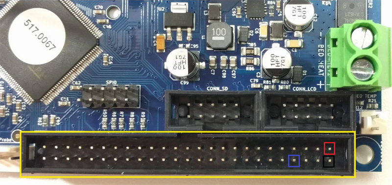
                From the Duet WiFi 1.03 PCB Expansion header

                PIN 1: +5 VDC to Module + Terminal (VCC +5)
                PIN 2: GND to Module - Terminal (GND)
                PIN 8: HEATER3 to Module Signal (S)

                12 VDC 5A Power Supply to Module POWER (VPP/GND)

                MOSFET_4CH_DIAGRAM.png

                DUETWIFIEXP.png

                1 Reply Last reply Reply Quote 0
                • First post
                  Last post
                Unless otherwise noted, all forum content is licensed under CC-BY-SA