Robotic kinematics
-
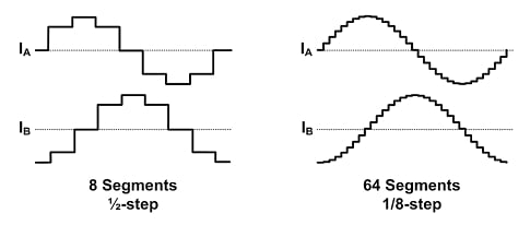
@tony73 I don't have a general link, but to explain for what microstepping is good, this https://hackaday.com/2016/08/29/how-accurate-is-microstepping-really/ is a good article. Microstepping is for smooth and quiet movement of the steppers, not for precision.
Interpolation means, like in mathematics, dedicating the position from known positions. The known positions are the full and half steps, the microsteps are the interpolated positions.
Separate explanation of interpolation: a stepper has a number of magnets and coils, those produce the full steps (not 1:1, but the result are 200 full steps), and through current manipulation, the steps between can be set, called interpolation. But both are not exact locations, steps have 5% position error and microsteps even more.
And when you power on, the stepper can have +- 2 steps difference from the position when you powered off. One of the reasons why one needs homing and not simply storing the last position when powering off.
To understand 16 I1, it is important to know that the firmware sends 16 microsteps, and the trinamic driver interpolates to 256 steps inside the driver. If you set 256 I0 e.g. the firmware has to generate all 256 steps, which is too much in most cases, resulting in lost steps and movement errors (M122 reports hiccups then).
-
Interpolation gives you a smoother wave-form, but you don't need to generate the extra steps (you'll have to imagine a 1/256th wave that is really smooth!)
Its mostly a benefit for noise, although for some applications you might actually be able to see that the motion is more smooth.
-
I reintroduced the A parameter to define min and max angles for the 5 axis and don't use M208 in the future. The reason is, M208 is based on the assumption that world coordinates are used and the area is rectangle. At robots this is not true, the allowed area differs with the Z value (looks a bit like a donut), so the limits are better and exact controlled by the angles instead.
Using M208 to define angles like I did may conflict with existing firmware code where M208 is used, so I better use the separate parameter A to define the angles. This is also more similar to the other scara kinematics.I introduced a new parameter D to define the outline of the arms and axis, based on a research article how to avoid collisions when two robots are working in the same working area. To allow easier calculation, the arms are outlined by a cylinder and the actuator by a sphere. This will also allow to control that arm 5's extruder is not in the way of arm 3 if arm 3 is near horizontal position.
The necessary firmware changes for A and M208 will be done next weekend, D will take a while. I've implemented it and check it in and it compiles, but it is not tested yet.
-
@tony73 I found a reason for your problems.
The G92 and M114 use X, Y and Z as cartesian coordinates, other letters like U and V as the firmware defines it, in this case angles.
So the endstop position of axis 1 to 3 cannot be set with G92.
M114 behaves the same, i.e. X, Y, Z are coordinates, not angles. U and V are angles.
I introduced additional values to the A parameter now, to specify the endstop positions. I removed limits of M208, M208 is not used.
The changes are checked in and compile ok, but not tested.
-
@JoergS5
thanks for the explanation of the interpolated microstepping! I saw that you were eliminating M208 and putting back parameter A to limit the angles, if I have not misunderstood now there is a minimum angle, a maximum angle and a point always in degrees where the limit switch for each actuator would be! -
@tony73 yes, I think this is the easiest way to specify the properties and avoiding confusion between angles and coordinates.
The limit switch is the endstop, but it can be everywhere, not necessary at an end. For axis 1, it will often be at 0 degree.
A problem is that the reporting output maximum length is limited and will abbreviate the output of the parameters. I'll search where it' s handled and will make it larger for Duet3, but this would be a request for David. I could program that with M669 A are only reported the A values as an alternative.
-
i went to fiveaxisrobot kinematic.h end stop angles and axis limit min and max to understand how to set the angles in m669, tomorrow i will try on duet 3 (only motors and limit switches connected) to see what they do .you managed to try yours robot with these changes? with end stop angles that you added to parameter A, is it now possible to make the robot assume any position in the homing phase, and he will know that he is at a certain degree from his min and max limits of each actuator?
-
@JoergS5 said in Robotic kinematics:
A problem is that the reporting output maximum length is limited and will abbreviate the output of the parameters. I'll search where it' s handled and will make it larger for Duet3, but this would be a request for David.
It's likely that I will change the output mechanism to remove the limitation on output length in 3.2beta3. I have already done the preparatory work.
Duet WiFi hardware designer and firmware engineer
Please do not ask me for Duet support via PM or email, use the forum
http://www.escher3d.com, https://miscsolutions.wordpress.com -
@dc42 thank you, then I don't need to change it and use the workaround.
-
@tony73 said in Robotic kinematics:
is it now possible to make the robot assume any position in the homing phase, and he will know that he is at a certain degree from his min and max limits of each actuator
I am not sure whether we have a common understanding.
When the printer powers up, the following procedure is made for each axis:
- he doesn't know where the position of the stepper and hence the angle is
- he needs to rotate the stepper/angle to find the endstop
- when he found the endstop, he now knows through the A endstop position at which angle it is. The firmware stores the stepper position as liveCoordinates/motorPos and can calculate the cartesian coordinates when all home angles are set by homing all axes.
- through the A angle limits he knows how much he is allowed to rotate to min and max
Step 2 is difficult because the angle could be anywhere, so the printer doesn't know whether he should rotate left or right. One strategy would be to rotate left a bit, then right a bit more etc. until found. This could be a strategy for axis 1. Another strategy is to have the arm in a defined position when power off, so the printer can find the endstop by rotating in a specific direction. This could be a good strategy for axis 2 and 3. A third strategy could be that an external solution like a camera can tell the firmware where the arms are roughly and in which direction the printer can find the endstops. (I'll make a proposal in the homing document when I have a good solution. Maybe strategy 2 is best, because when power off, the arms could fall down. It is good to have a secure "parking position" anyway).
The endstops can be defined at high or low end, it doesn't matter for the M669 setting (but in config you must use one). For finding the angle, it would be good to approach the endstop always from the same direction, most endstops will differ with direction.
I have to test whether when using G1 H1 while homing needs a dummy M208, it may produce an error message when there is no M208.
-
Hello! I'm sorry but sometimes it is not easy to explain a concept, I think I understand the new A parameters you added I did these tests with a 3d program that I use like fusion 360, I only have the motors and the end stops, but it seems that the things are fine, there are small differences of hundredths or tenths, but it could be normal, except actuator 5 which continues to mark V 5.005 after homing, before homing and V 0.0
in both cases I can move in the X Y Z coordinates, always respecting the MIN MAX degree limits of the actuators, for the famous reachable area like gianbella!M669 K13 X0.0:0.0 Y0.0:0.0 Z100.0 L200.0:200.0:100.0:0.0 R0 P2:45 C0 A-45.0:0.0:45.0:0.0:45.0:90.0:-110.0:-90.0:0.0:-170.0:-45.0:0.0:-225.0:0.0:225.0:0.0:0.0:1000.0
this and M669 used for the graph below
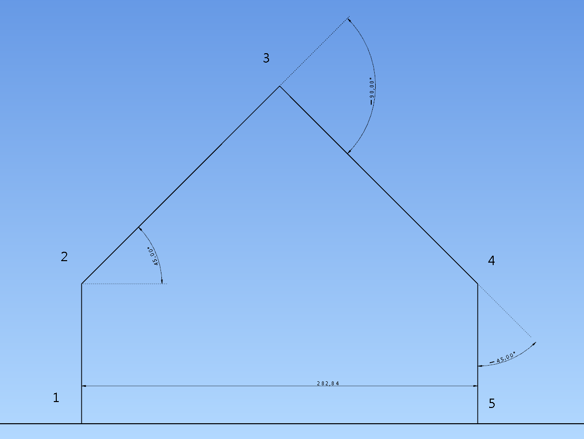
height Z should be 0 after homing and X 282.84
M114 I from Z-0.002 and X 282.843 Y0.0 U-45 V5.005
M669 K13 X0.0:0.0 Y0.0:0.0 Z100.0 L200.0:200.0:100.0:0.0 R0 P2:45 C0 A-45.0:0.0:45.0:0.0:138.0:150.0:-160.0:-149.0:0.0:-170.0:-79.0:0.0:-225.0:0.0:225.0:0.0:0.0:1000.0this is the second M669 test
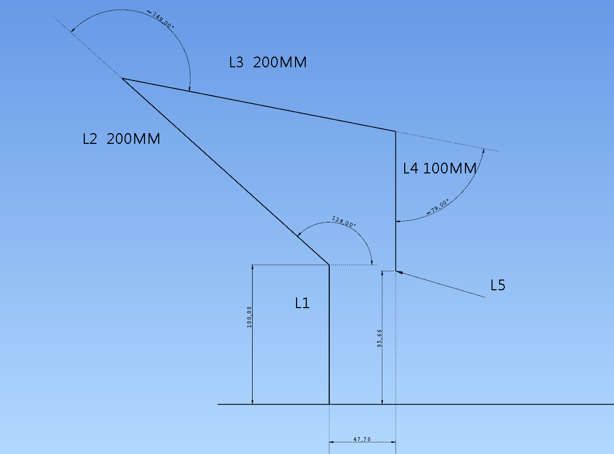
height Z should be 95.66 after homing and X 47.70
M114 I from Z95.666 and X 47.717 Y0.0 U-78.989 V5.005the images are along the X axis
when I send M114 before homing the axes are all at zero X 0.0 Y0.0 Z0.0 U0.0 V0.0 after homing the only strange thing is V which becomes V5.005 -
@tony73 I am glad that there is some progress. Some of the angle errors may be from the trigonometric function being not exact, but I will check with my calculations. The V value is strange, I will analyze it separately. One reason could be that arm 5 length is 0, so the angle 5 doesn't play a role for the position calculation. But of course for the hotend direction it's important.
-
@tony73 could you please test the M114 results if you set M92 values to values with .0, e.g.
M92 X779.0 Y838.0 Z1067.0 U420.0 V71.0
This should diminish the Z error. If you can confirm it, I will try to find a solution.=> I tested a bit, changing all float to double in internal calculations. This halfes the errors, but not to 0. The G-Code stepsPerMm are read in as float always, changing it to double would yield this halfing, but this is deep intern of the firmware, changing has some effort.
-
@JoergS5
Hello! later I try M92 with .0 I'll let you know! I'm sorry but I have little time to devote these days! -
@tony73 no problem, no hurry. I myself am proceeding building the new version of the prototype, concentrating on a good design for the gears.
-
here are the results!
M92 X778.0 Y838.0 Z1066.0 U71.0 V71.0 : M92 CALCULATION WITH .0
M92 X778.67 Y838.10 Z1066.67 U71.11111111 V71.11111111 :M92 NORMAL CALCULATION THAT I HAD IN CONFIG.G
M669 K13 X0.0:0.0 Y0.0:0.0 Z100.0 L200.0:200.0:100.0:0.0 R0 P2:45 C0 A-45.0:0.0:45.0:0.0:45.0:90.0:-110.0:-90.0:0.0:-170.0:-45.0:0.0:-225.0:0.0:225.0:0.0:0.0:1000.0
: X 282.84 Y0.000 Z 0.000 U-45.000 V ? : FIRST GRAPH RESULT OF THE REQUIRED CALCULATION
: X 282.843 Y 0.000 Z-0.002 U-45.000 V 5.005 : FIRST OLD TEST
: X 282.843 Y 0.000 Z 0.000 U-45.000 V 5.000 : FIRST NEW TEST
M669 K13 X0.0:0.0 Y0.0:0.0 Z100.0 L200.0:200.0:100.0:0.0 R0 P2:45 C0 A-45.0:0.0:45.0:0.0:138.0:150.0:-160.0:-149.0:0.0:-170.0:-79.0:0.0:-225.0:0.0:225.0:0.0:0.0:1000.0
: X47.70 Y 0.000 Z 95.66 U-79.000 V ? : SECOND GRAPH RESULT OF THE REQUIRED CALCULATION
: X 47.717 Y0.000 Z95.666 U-78.989 V5.005 : SECOND OLD TEST
: X 47.696 Y 0.000 Z 95.664 U-79.000 V 5.000 : SECOND NEW TEST
in the first new test Z becomes 0.000 as calculated by the graph, in the second new test U becomes -79.000 as calculated by the graph, removing the decimals from M92 the result improves!
I see that V from 5,005 becomes 5,000
-
@tony73 thanks for testing, this is similar to my test result in the windows based tests. It seems to be rounding errors, I didn' t find another reason. btw z0.002 error is not so much, only 2 micrometer. But I would prefer exact results.
=> the inexactness comes from the converting float to motor position integers, using .0 doesn't produce such converting error. This error of Z0.002 will be unavoidable sometimes, because the motor cannot be positioned to the exact position in any constellation.When I change all calculations to double inclusive the stepsPerDegree, the errors are halved, but not zero. But there is no function to read G-Code values as double.
I tested multiplying the steps by 10 with .0 each, y8381.0 e.g., but the errors reappear then.
The V should be 45 because of axis 1 being 0 and P2:45, and my tests give back this angle also. I will find the reason!
I analyzed M114 a bit. The values after Count are the motorPos values. They are integer values and are angle*stepsPerDegree. (stepsPerDegree = m92 values)
-
@JoergS5
good morning! to use P3 mode, just put P3 in M669 or should I add something to the firmware? could you explain to me? -
@tony73 just use P3 instead of P2:45.
-
@JoergS5
I asked you this because I tried to put P3 and I saw a strange behavior of motor 5 when I send G1 XY commands, considering that I only look at a motor that moves its axis and not having set an offset between the motor shaft and extruder L5 = 0.0, what should I see if I move the robot (motors!) With G1 or simulating a print with a g.code? I would like to understand how the P3 command behaves