Conneting heatbed, temp readings ok but not heating up
-
Hello again
")
So i outfitted my printer with a heatbed (was printing pla the whole time, so why bothering with one) and i cannot get it to work

It is this one and i can't get it to heat up. There is no info about the thermistor, so it took the info about the resistance from the webpage:
6. Widerstand ca. 0,9 Ohm bei 12V
7. Widerstand ca. 3,6 Ohm bei 24V ( i am running the system on 24V).My line in config.g looked like this:
M308 S1 P"bedtemp" Y"thermistor" T3600 B734Result temp: -273.1
Clearly the wrong thinking on my end, i then changed it to the EPCOS 100K:
M308 S1 P"bedtemp" Y"thermistor" T100000 B4092Result temp: 23.3 (same as hotend readings, sometimes deviating 0.1 to 0.3 degrees)
Great, thermistor works. Changing the status of the heatbed to active (65 degree), doesn't even start to heat, stays at 23.3° and giving this message:
Error: Heater 0 fault: temperature rising much more slowly than the expected 1.8°/secChanging again:
M308 S1 P"bedtemp" Y"thermistor" T10000 B3988Result temp: -273.1
Then [M308 S1 P"bedtemp" Y"thermistor" T100000 B3950](link url)
Result temp: 23.3So it is definetly a 100K thermistor. But it is giving the same error message as above when i try to heat up the bed.
Mosfet on the duet looks good, nothing burned etc. I wired the heatbed directly to the board, over a mosfet, changed polarity...!Is there anything i am doing completly wrong or is the heatbed faulty?
Btw. the heatbed came soldered like this, maybe here is some work to do (resolder, when to measure what to measure...)?

Thx in advance
-
you would be better posting your config.g file in full
And which version of firmware etc -
Ok, maybe there is something i missed (DWC is: Duet Web Control 3.1.1.).
Everything else works fine. Still able to print.; Configuration file for Duet WiFi (firmware version 3) ; executed by the firmware on start-up ; ; generated by RepRapFirmware Configuration Tool v3.1.1 on Sun Jun 07 2020 20:42:24 GMT+0200 (Mitteleuropäische Sommerzeit) ; General preferences G90 ; send absolute coordinates... M83 ; ...but relative extruder moves M550 P"Anet AM8" ; set printer name M575 P1 B57600 S1 ; Comms parameters for PanelDue ; Network M552 S1 ; enable network M586 P0 S1 ; enable HTTP M586 P1 S1 ; enable FTP M586 P2 S0 ; disable Telnet ; Drives M569 P0 S1 ; physical drive 0 goes forwards M569 P1 S1 ; physical drive 1 goes forwards M569 P2 S1 ; physical drive 2 goes backwards M569 P3 S1 ; physical drive 3 goes forwards ;M569 P4 S1 ; physical drive 4 (E1) goes forwards M584 X0 Y1 Z2:2 E3 ; set drive mapping M350 X16 Y16 Z16 E16 I1 ; configure microstepping with interpolation M92 X80.00 Y80.00 Z400.00 E396.83 ; set steps per mm M566 X360.00 Y360.00 Z12.00 E3600.00 ; set maximum instantaneous speed changes (mm/min) M203 X6000.00 Y6000.00 Z180.00 E6000.00 ; set maximum speeds (mm/min) M201 X1500.00 Y1500.00 Z500.00 E5000.00 ; set accelerations (mm/s^2) M906 X1400 Y1400 Z1400 E1400 I30 ; set motor currents (mA) and motor idle factor in per cent M84 S30 ; Set idle timeout ; Axis Limits M208 X-50 Y-20 Z0 S1 ; set axis minima M915 X Y S30 R2 F1 ; set X and Y to sensitivity 30, pause when stall, filtered M208 X250 Y250 Z240 S0 ; set axis maxima ; Endstops M574 X1 S3 ; configure sensorless endstop for low end on X M574 Y1 S3 ; configure sensorless endstop for low end on Y M574 Z1 S2 ; configure Z-probe endstop for low end on Z ; Z-Probe M950 S0 C"exp.heater3" ; create servo pin 0 for BLTouch M558 P9 C"zprobe.in" H5 A5 S0.03 F120 T6000 ; set Z probe type to switch and the dive height + speeds G31 P500 X30 Y0 Z1.65 ; set Z probe trigger value, offset and trigger height M557 X20:200 Y20:200 S40 ; define mesh grid ; Heaters M308 S0 P"e0temp" Y"thermistor" T100000 B4725 C7.06e-8 ; configure sensor 0 as thermistor on pin e0temp M950 H1 C"e0heat" T0 ; create nozzle heater output on e0heat and map it to sensor 0 M307 H1 B0 S1.00 ; disable bang-bang mode for heater and set PWM limit M308 S1 P"bedtemp" Y"thermistor" T100000 B3950 ; configure sensor 1 as thermistor on pin bedtemp M950 H0 C"bedheat" T1 ; create bed heater output on bedheat and map it to sensor 1 M307 H0 B0 S1.00 ; disable bang-bang mode for the bed heater and set PWM limit M140 H0 ; map heated bed to heater 1 M143 H0 S120 ; set temperature limit for heater 1 to 120C ; Fans M950 F0 C"fan0" Q500 ; create fan 0 on pin fan0 and set its frequency M106 P0 S0 H-1 ; set fan 0 value. Thermostatic control is turned off M950 F1 C"fan1" Q500 ; create fan 1 on pin fan1 and set its frequency M106 P1 S1 H T45 ; set fan 1 value. Thermostatic control is turned on ; Tools M563 P0 D0 H1 F0 ; define tool 0 G10 P0 X0 Y0 Z0 ; set tool 0 axis offsets G10 P0 R0 S0 ; set initial tool 0 active and standby temperatures to 0C ; Custom settings are not defined ; Miscellaneous M501 ; load saved parameters from non-volatile memory T0 ; select first tool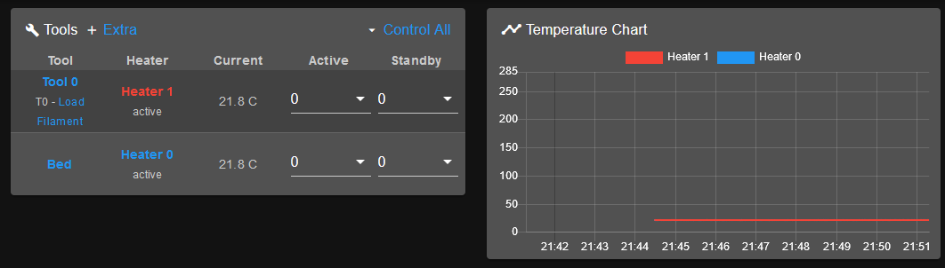
-
You're getting the error that it's heating up too slowly because RRF3 doesn't know it's a heatbed that heats slow. You need to PID tune the bed heater so it has a model of its performance.
-
I tried already to tune the bed.
But it aborted because the heatbed was not heating up.
The PID part in config-override.g:
M307 H0 A340.0 C140.0 D5.5 S1.00 V0.0 B0
M307 H1 A261.6 C97.4 D3.1 S1.00 V23.9 B0
I am thinking, the heatbed isn't getting any signal from the board (V= 0.0).
Is there a way to measure the voltage to find out where on the board it is broken or if only the connector is faulty? Got an multimeter at hand.
There are no burned spots etc, everything looks fine.
-
Ah I see, so the bed isn't actually heating at all.
Have you checked the voltage at the source pins on the board and at the bed itself with a multimeter?
-
So sorry for not responding earlier. Lot of work and some private things to sort out. And i ordered a multimeter for measuring
I never needed to measure anything electrical, so i am a little noob on that end. But always willing to learn new stuff.
So i am turning duet board on, than the wheel to 20V DC (or AC??) and then pointing the black one on the screw of the heatbed connector and the red one to point 1/2/3 at the heatbed (pic in OP)?

-
I'd suggest having a read of the manual for the meter. It will be able to give much better and accurate directions than I could. But in general, you want to measure the DC voltage at the bed terminals on the duet side and at the bed side.