Random no trigger from BL Touch
-
I am running genuine parts. My BL Touch randomly will fail the Mesh bed compensation test at different points. When it failes, it just crashes into the bed. I reset and re-home everything. The homing always works. But sometimes I get a complete compensation test, sometimes I crash..
I've read that we are supposed to delete the deploy and retract .g files? Is that still true on the 2.05 firmware? (That's what I'm running) I was able to do some printing finally yesterday and I'm very excited to see that! But was disappointed today when I went to start the calibration tests and now dealing with this..
Here's what I have in my config.g
; Configuration file for Duet WiFi (firmware version 1.21)
; executed by the firmware on start-up
;
; generated by RepRapFirmware Configuration Tool v2 on Fri May 24 2019 20:44:40 GMT-0500 (Central Daylight Time); General preferences
G90 ; Send absolute coordinates...
M83 ; ...but relative extruder moves; Network
M550 P"3DPrinter" ; Set machine name
M552 S1 ; Enable network
M586 P0 S1 ; Enable HTTP
M586 P1 S0 ; Disable FTP
M586 P2 S0 ; Disable Telnet; Drives
M569 P0 S0 ; Physical drive 0 goes Backwards
M569 P1 S0 ; Physical drive 1 goes Backwards
M569 P2 S1 ; Physical drive 2 goes forwards
M569 P3 S0 ; Physical drive 3 goes forwards;current settings
M584 X0 Y1 Z2:4 E3; two Z motors connected to driver outputs Z and E1
M671 X-81.5:291.5 Y110:110 S2 ; leadscrews at left (connected to Z) and right (connected to E1) of X axisM350 X16 Y16 Z16 E16 I1 ; Configure microstepping with interpolation
M92 X99.9 Y100.1 Z399.6183 E99. ; Set steps per mm
M566 X900.00 Y900.00 Z12.00 E110.00 ; Set maximum instantaneous speed changes (mm/min)
M203 X6000.00 Y6000.00 Z4000.00 E1200.00 ; Set maximum speeds (mm/min)
M201 X500.00 Y500.00 Z20.00 E250.00 ; Set accelerations (mm/s^2)
M906 X1100.00 Y1100.00 Z1100.00 E1100.00 I30 ; Set motor currents (mA) and motor idle factor in per cent
M84 S30 ; Set idle timeout; Axis Limits old
;M208 X20 Y0 Z0 S1 ; Set axis minima
;M208 X230 Y210 Z200 S0 ; Set axis maxima;New Settings
M208 X-20:230 Y-20:230 ; X carriage moves from 0 to 210, Y bed goes from 0 to 210; Endstops
M574 X1 Y1 S1 ; Set active high endstops; Z-Probe
M574 Z1 S2 ; Set endstops controlled by probe
M307 H3 A-1 C-1 D-1 ; Disable heater on PWM channel for BLTouch
M558 P9 H10 F500 T4000 X0 Y0 Z1 ; Set Z probe type to bltouch and the dive height + speeds (F100 T2000 original settings)
G31 P25 X34.82 Y-8 Z-0.033 ; Set Z probe trigger value, offset and trigger height
M557 X0:210 Y15:210 S52.5 ; Define mesh grid; Heaters
M305 P0 T100000 B4138 R4700 ; Set thermistor + ADC parameters for heater 0
M143 H0 S120 ; Set temperature limit for heater 0 to 120C
M305 P1 T100000 B4725 C7.060000e-8 R4700 ; Set thermistor + ADC parameters for heater 1
M143 H1 S280 ; Set temperature limit for heater 1 to 280C; Fans
M106 P0 S0 I0 F500 H T45 ; Set fan 0 value, PWM signal inversion and frequency. Thermostatic control is turned on
M106 P1 S1 I0 F500 H1 T45 ; Set fan 1 value, PWM signal inversion and frequency. Thermostatic control is turned on; Tools
M563 P0 D0 H1 ; Define tool 0
G10 P0 X0 Y0 Z0 ; Set tool 0 axis offsets
G10 P0 R0 S0 ; Set initial tool 0 active and standby temperatures to 0C; Automatic saving after power loss is not enabled
; Custom settings are not configured
; Miscellaneous
M501 ; Load saved parameters from non-volatile memorybed.g
;Suggested settings from the Duete3D Dozuki.com
G28 ; home
;M401 ; deploy Z probe (omit if using bltouch)
G30 P0 X35 Y105 Z-99999 ; probe near a leadscrew, half way along Y axis
G30 P1 X205 Y105 Z-99999 S2 ; probe near a leadscrew and calibrate 2 motors
;M402 ; retract probe (omit if using bltouch)I still have deploy.g and retract.g in my files..
-
@hbrownell said in Random no trigger from BL Touch:
I've read that we are supposed to delete the deploy and retract .g files?
Only for probes that don't need to deploy or retract. For the BLTouch you need deploy and retract files and they need the correct commands to deploy and retract the pin. M401 and M402 should work to deploy and retract the pin. If they don't your commands in those files may be wrong.
Does your BLTouch deploy and retract the pin at power up?
It sounds like your pin is working most of the time, but sometimes it isn't triggering? Or is it sometimes not deploying?
Your M558 command is not quite right. Your probe speed is way too fast.
Try
M558 P9 H5 F120 T6000 A5 R0.5for starters.Your G31 trigger height is Z-0.033 which sounds very wrong. That would mean that the nozzle is already hitting the bed before the probe is triggered. When installed correctly the trigger height should be ~2mm
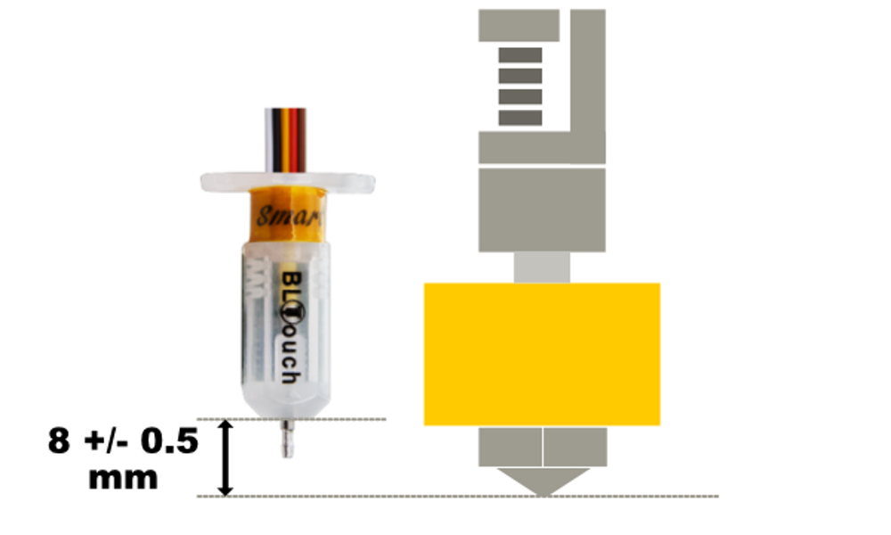
The base of the probe should be ~8mm above the nozzle tip.
See here for calibrating the trigger height.
https://duet3d.dozuki.com/Wiki/Test_and_calibrate_the_Z_probe -
I've gone back and forth with those numbers for the trigger height and I'm not convinced it actually changes anything. I had an override file, but I got rid of it for fear of redundancy where I didn't think it would be. My BL Touch is set up just like you say it should be. I plugged in 2mm and it crashed on the bed at 0. The number that seems to fit is the -.033 should I add more washers to make up the difference?
One other thing I'm wondering is where do I define the mesh compensation area? I notice a spot in the web control, but it's temporary. I'd rather not have to reset that every time.
One other thing I noticed was that when it crashed, I had the bed heat on, could that cause a problem ?
-
I did another check and I'm at 9mm above.
-
Mesh compensation is defined in M557. https://duet3d.dozuki.com/Wiki/Gcode#Section_M557_Set_Z_probe_point_or_define_probing_grid
If you do the trigger height calibration described here, what is the resulting value? https://duet3d.dozuki.com/Wiki/Test_and_calibrate_the_Z_probe
The head bed being on might have an effect. Some bed heaters can create a magnetic field that can interfere with the BLtouch probe. You can add B1 to the end of you M558 to test turning off the bed during probing.
If you're 9mm above try dropping it down 1mm.