Need help understanding wiring custom-ish hardware
-
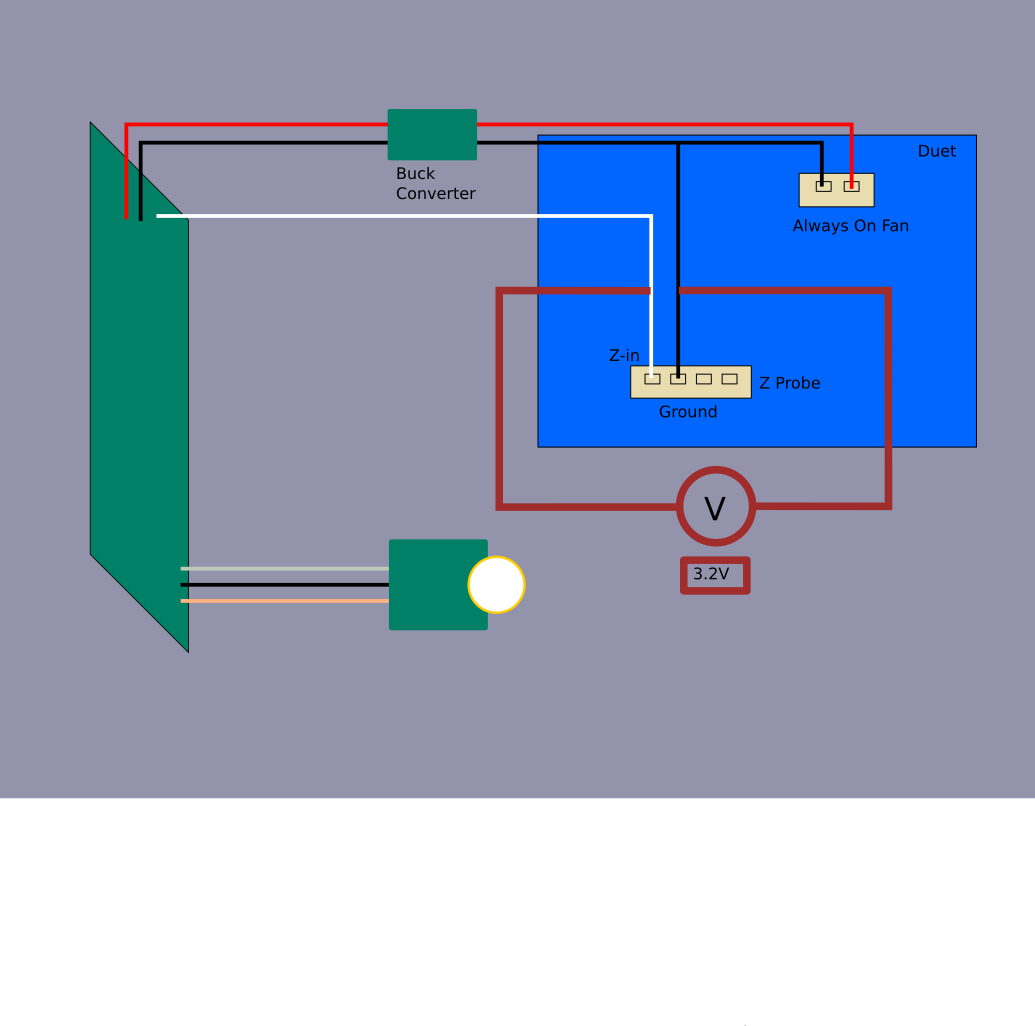
I have an EasyPiezi for under bed z probe. I'm just not sure how it should be wired.
There is positive and negative that get power from the always on fan connector. That goes through a buck converter to feed the EP control board.
There is a single signal wire to send to the Duet.
End switches and z probe connectors expect a ground afai understand.
Some background questions...
How do end stop connections work with simple NC switches? There are only the signal and ground leads connected. Is the signal providing voltage that returns through ground?
How do the other modes for switches work that have three wires?
The instructions I've received say to connect the ground that normally accompanies the signal on the switch connector to the ground coming from the fan header. That seems strange considering there is a buck converter between the fan header and the board.
When it comes to M950 pin configuration, do the different modes switch between voltage providing and voltage sensing?
The vendor says the EP only sends a signal for 20 microseconds, is that long enough to trigger the end stop?
-
@gnydick said in Need help understanding wiring custom-ish hardware:
EasyPiezi
looking at their documentation
https://docs.pyroballpcbs.com/tutorials/wiring/easy-piezi/unregulated-operation/
then you can connect it directly to the z probe 3.3v pin
-
I don't have micro-soldering tools to do that

-
ok but since the EasyPiezi has an input range of 6-40V why do you need a buck converter?
-
which version did you get? the 12v or the over 12v?
-
this is the wiring for duet
https://docs.pyroballpcbs.com/tutorials/wiring/pp-ffc/duet-wifi/
-
@Veti because it can't actually handle the 24v. I've been working with the engineer at pyro.
-
so you got the 12v version and not the over 12v version?
-
you could try a Silver Conductive Paint Pen if you dont have a soldering iron
-
@Veti interesting