Solved Wifi Module Issue - Failed to get Wifi Status
-
Hello all,
I have a Duet2 with Wifi module which is able to connect to a Wifi network but I am not able to connect to the web client.The duet2 board originally had a failed ESP12S module. It was not able to start despite multiple firmware updates and error.
This has been replaced by a new ESP07S module.
It has been flashed to duet Wifi 1.02 with the main board running on v2.03.
The network SSID and password has been configured and this is the only saved network.
It connects to this network and an IP is given out. A ping command confirms some form of comms.
Connecting to the web interface results in a connection timeout.Results of an M122 command below, as well as a M111 P14 S1 then disabling and enabling the module.
There appears to be an issue with sending / receiving messages to/from the ESP (my guess). If so there might be a physical issue as well - visually the board looks fine however.
Thanks in advance for any help!
M122:
=== Diagnostics ===
RepRapFirmware for Duet 2 WiFi/Ethernet version 2.03 running on Duet WiFi 1.02 or later
Board ID: 08DGM-956GU-DJ3SN-6JKFG-3S86J-1ARMG
Used output buffers: 1 of 24 (10 max)
=== RTOS ===
Static ram: 25680
Dynamic ram: 93304 of which 0 recycled
Exception stack ram used: 256
Never used ram: 11832
Tasks: NETWORK(ready,1380) HEAT(blocked,1236) MAIN(running,3756) IDLE(ready,160)
Owned mutexes: WiFi(NETWORK)
=== Platform ===
Last reset 00:34:50 ago, cause: software
Last software reset time unknown, reason: User, spinning module GCodes, available RAM 9092 bytes (slot 1)
Software reset code 0x0003 HFSR 0x00000000 CFSR 0x00000000 ICSR 0x00433000 BFAR 0xe000ed38 SP 0xffffffff Task 0x4e49414d
Error status: 0
Free file entries: 10
SD card 0 detected, interface speed: 20.0MBytes/sec
SD card longest block write time: 0.0ms, max retries 0
MCU temperature: min 30.8, current 31.1, max 31.5
Supply voltage: min 1.6, current 1.6, max 1.7, under voltage events: 0, over voltage events: 0, power good: no
Driver 0: ok, SG min/max not available
Driver 1: ok, SG min/max not available
Driver 2: ok, SG min/max not available
Driver 3: ok, SG min/max not available
Driver 4: ok, SG min/max not available
Date/time: 1970-01-01 00:00:00
Cache data hit count 4294967295
Slowest loop: 145.11ms; fastest: 0.06ms
I2C nak errors 0, send timeouts 0, receive timeouts 0, finishTimeouts 0, resets 0
=== Move ===
Hiccups: 0, FreeDm: 169, MinFreeDm: 169, MaxWait: 0ms
Bed compensation in use: none, comp offset 0.000
=== DDARing ===
Scheduled moves: 0, completed moves: 0, StepErrors: 0, LaErrors: 0, Underruns: 0, 0
=== Heat ===
Bed heaters = -1 -1 -1 -1, chamberHeaters = -1 -1
=== GCodes ===
Segments left: 0
Stack records: 2 allocated, 0 in use
Movement lock held by null
http is idle in state(s) 0
telnet is idle in state(s) 0
file is idle in state(s) 0
serial is ready with "m122" in state(s) 0
aux is idle in state(s) 0
daemon is idle in state(s) 0
queue is idle in state(s) 0
autopause is idle in state(s) 0
Code queue is empty.
=== Network ===
Slowest loop: 401.09ms; fastest: 0.00ms
Responder states: HTTP(0) HTTP(0) HTTP(0) HTTP(0) FTP(0) Telnet(0) Telnet(0)
HTTP sessions: 0 of 8
- WiFi -
Network state is running
WiFi module is connected to access point
Failed messages: pending 0, notready 0, noresp 224
Failed to get WiFi status
Socket states: 0 0 0 0 0 0 0 0
M111 P14 S1 then disabling and enabling the wifi module
m552 s-1 WiFi module stopped ok M552 s0 WiFi: WiFi: ets Jan 8 2013,rst cause:2, boot mode:(3,6) WiFi: WiFi: load 0x4010f000, len 1384, room 16 WiFi: tail 8 WiFi: chksum 0x2d WiFi: csum 0x2d WiFi: v3fff168c WiFi: ~ld ok WiFi module started M552 s1 ok WiFi: WiFi: add if0 WiFi: wifi evt: 8 WiFi: scandone WiFi: ../src/SocketServer.cpp(353): found network ***** WiFi: ../src/SocketServer.cpp(353): found network ***** WiFi: ../src/SocketServer.cpp(353): found network WiFi: ../src/SocketServer.cpp(353): found network J*********C WiFi: ../src/SocketServer.cpp(353): found network ***** WiFi: sleep enable,type: 2 WiFi: wifi evt: 2 WiFi: scandone WiFi: state: 0 -> 2 (b0) WiFi: state: 2 -> 3 (0) WiFi: state: 3 -> 5 (10) WiFi: add 0 WiFi: aid 1 WiFi: cnt WiFi: WiFi: connected with JunctionCNC, channel 11 WiFi: dhcp client start... WiFi: wifi evt: 0 WiFi: ip:192.168.1.204,mask:255.255.255.0,gw:192.168.1.1 WiFi module is connected to access point J*********C, IP address 192.168.1.204 WiFi: wifi evt: 3 WiFi: pm open,type:2 0 -
Can you try updating the main firmware (to 2.05.1) and wifi server firmware (to 1.23) and make sure you have the DWC (version 2.0.7) files present in the /www folder.
-
@Phaedrux
Thanks for the reply. Yes will do on Tuesday when I'm back in the workshop.
As a side note the firmwares used are the latest for Ooznest CNC control as this board is intended to run a small CNC machine. So ideally I'd be looking to roll back to these if all can be made to work.
I'll report back once this is done. -
This post is deleted! -
Hello,
OK I have updated to firmwares to those from here. Duet to 2.05.1 and Wifi to 1.23.
I have the same issue as before. Wifi connects to the network and DHCP gives an IP. Ping works with low latency. HTTP requests appears to time out.
I enabled debugging for the HTTP Server (M122 P2 S1). Initially after updating the Wifi module firmware, I ran commands logged below. I then enabled debugging on HTTP Server and tried to connect I got the response (over serial) listed below. I'm not able to recreate this now - I've tried hard restart, reflashing the Wifi firmware, and disabling and re-enabling HTTP debugging. In browser network stack the network section does not show any connection to the Duet or response from it - not even headers.
All and any suggestions gratefully received!
HTTP Debugging enabled - cannot recreate this response however. All other connections show no response on the debugger:
M111 P2 S1
Debugging enabled for modules: Webserver(2) WiFi(14)
Debugging disabled for modules: Platform(0) Network(1) GCodes(3) Move(4) Heat(5) DDA(6) Roland(7) Scanner(8) PrintMonitor(9) Storage(10) PortControl(11) DuetExpansion(12) FilamentSensors(13) Display(15)
ok
HTTP connection accepted
HTTP req, command words { GET / HTTP/1.1 }, parameters { }
Sending reply, file = yes
HTTP connection accepted
HTTP connection accepted
HTTP req, command words { GET /js/app.ab1d3899.js HTTP/1.1 }, parameters { }
Sending reply, file = yes
HTTP req, command words { GET /css/app.db918b7e.css HTTP/1.1 }, parameters { }
Sending reply, file = yes
Can't send anymore
M122:
m122
=== Diagnostics ===
RepRapFirmware for Duet 2 WiFi/Ethernet version 2.05.1 running on Duet WiFi 1.02 or later
Board ID: 08DGM-956GU-DJ3SN-6JKFG-3S86J-1ARMG
Used output buffers: 1 of 24 (2 max)
=== RTOS ===
Static ram: 25712
Dynamic ram: 92800 of which 0 recycled
Exception stack ram used: 264
Never used ram: 12296
Tasks: NETWORK(ready,540) HEAT(blocked,1232) MAIN(running,4076) IDLE(ready,160)
Owned mutexes: WiFi(NETWORK)
=== Platform ===
Last reset 00:01:07 ago, cause: power up
Last software reset time unknown, reason: User, spinning module GCodes, available RAM 9092 bytes (slot 1)
Software reset code 0x0003 HFSR 0x00000000 CFSR 0x00000000 ICSR 0x00433000 BFAR 0xe000ed38 SP 0xffffffff Task 0x4e49414d
Error status: 0
Free file entries: 10
SD card 0 detected, interface speed: 20.0MBytes/sec
SD card longest block write time: 0.0ms, max retries 0
MCU temperature: min 24.7, current 26.1, max 26.5
Supply voltage: min 1.4, current 1.6, max 1.7, under voltage events: 0, over voltage events: 0, power good: no
Driver 0: ok, SG min/max not available
Driver 1: ok, SG min/max not available
Driver 2: ok, SG min/max not available
Driver 3: ok, SG min/max not available
Driver 4: ok, SG min/max not available
Date/time: 1970-01-01 00:00:00
Cache data hit count 345704244
Slowest loop: 159.04ms; fastest: 0.05ms
I2C nak errors 0, send timeouts 0, receive timeouts 0, finishTimeouts 0, resets 0
=== Move ===
Hiccups: 0, FreeDm: 160, MinFreeDm: 160, MaxWait: 0ms
Bed compensation in use: none, comp offset 0.000
=== DDARing ===
Scheduled moves: 0, completed moves: 0, StepErrors: 0, LaErrors: 0, Underruns: 0, 0
=== Heat ===
Bed heaters = -1 -1 -1 -1, chamberHeaters = -1 -1
=== GCodes ===
Segments left: 0
Stack records: 2 allocated, 0 in use
Movement lock held by null
http is idle in state(s) 0
telnet is idle in state(s) 0
file is idle in state(s) 0
serial is ready with "m122" in state(s) 0
aux is idle in state(s) 0
daemon is idle in state(s) 0
queue is idle in state(s) 0
autopause is idle in state(s) 0
Code queue is empty.
=== Network ===
Slowest loop: 1225.94ms; fastest: 0.00ms
Responder states: HTTP(0) HTTP(0) HTTP(0) HTTP(0) FTP(0) Telnet(0) Telnet(0)
HTTP sessions: 0 of 8
- WiFi -
Network state is running
WiFi module is connected to access point
Failed messages: pending 0, notready 0, noresp 112
Failed to get WiFi status
Socket states: 0 0 0 0 0 0 0 0
ok
M111 P14 S1 then disabling and enabling the wifi module:
m552 s-1 WiFi module stopped ok M552 s0 WiFi: WiFi: ets Jan 8 2013,rst cause:2, boot mode:(3,6) WiFi: WiFi: load 0x4010f000, len 1384, room 16 WiFi: tail 8 WiFi: chksum 0x2d WiFi: csum 0x2d WiFi: v3fff168c WiFi: ~ld ok WiFi module started m552 s1 ok WiFi: WiFi: add if0 WiFi: wifi evt: 8 WiFi: scandone WiFi: ../src/SocketServer.cpp(353): found network *** WiFi: ../src/SocketServer.cpp(353): found network *** WiFi: ../src/SocketServer.cpp(353): found network *** WiFi: ../src/SocketServer.cpp(353): found network J*********C WiFi: ../src/SocketServer.cpp(353): found network *** WiFi: sleep enable,type: 2 WiFi: wifi evt: 2 WiFi: scandone WiFi: state: 0 -> 2 (b0) WiFi: state: 2 -> 3 (0) WiFi: state: 3 -> 5 (10) WiFi: add 0 WiFi: aid 1 WiFi: cnt WiFi: WiFi: connected with J*********C, channel 11 WiFi: dhcp client start... WiFi: wifi evt: 0 WiFi: ip:192.168.1.204,mask:255.255.255.0,gw:192.168.1.1 WiFi module is connected to access point J*********C, IP address 192.168.1.204 WiFi: wifi evt: 3 WiFi: pm open,type:2 0 -
What happens when you place the wifi server 1.23 bin on the sd card in the sys folder and then send M997 S1 over serial? Does it successfully flash?
-
@Phaedrux
It flashes successfully. Connecting at the first baud rate and runs through the percentages until 100%. No errorsreportednoticed.
I can post a transcribe of this if useful?
I do notice that the first line of the M122 response shows Duet WiFi 1.02 not 1.23...?Main firmware flashes fine as well. Both flash in the same way as our other Duet, although I haven't compared the serial output line by line. I'll look again tomorrow.
The main difference I can see between our working board and this one is the end of the M122 response in - WiFi - : Failed messages: noresp: XXX, and Failed to get WiFi status. Although some communication must be taking place to get any status or firmware update..?
Thanks,
-
@maeterlinck said in Wifi Module Issue - Failed to get Wifi Status:
Duet WiFi 1.02 not 1.23
That's what the firmware detects as minimum the Duet PCB revision. 1.23 is the wifi server firmware version. Not related.
-
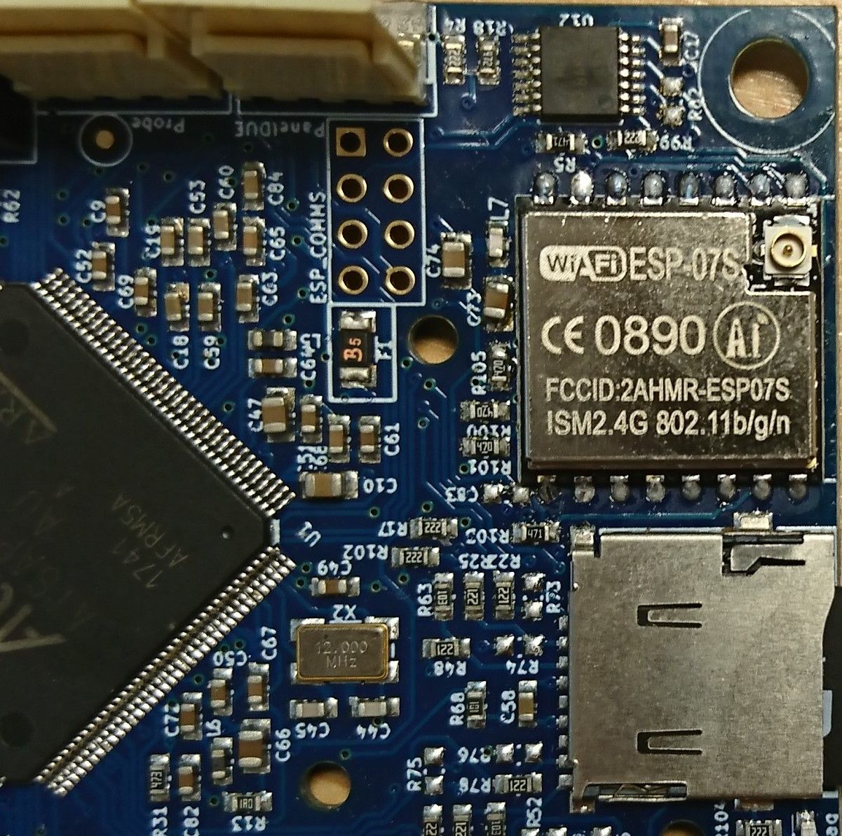
My guess is that either the wifi module is faulty, or one of the pins is not soldered to the pad, or that in replacing the WiFi module you accidentally disturbed or lost one of the resistors close to the WiFi module (which should be apparent if you post a photo of that area of the board).
Serial comms is used to flash the firmware and get debug info, but SPI comms is used for everything else. It may be that the SPI comms is only working in one direction.
Duet WiFi hardware designer and firmware engineer
Please do not ask me for Duet support via PM or email, use the forum
http://www.escher3d.com, https://miscsolutions.wordpress.com -
@dc42
Part of our work here is PCB design/assembly. Old module was removed with hot air and all pads were solid when cleaned up and retinned. The ESP-07S fitted was fresh out of the box. Not impossible to be faulty - just hopefully unlikely.Surrounding descretes match our working board - including DNPs - so I'm taking that as correct.
I had wondered about only one of the SPI lines working. Given the "noresp" in the M122 command then ESP>ATSAM.
I've worked through the PCB traces and confirmed continuity between pads on ESP, U12, U1, and the descretes (with a multimeter). I've also looked at the legs on the ICs under our microscope and the soldering looks fine.
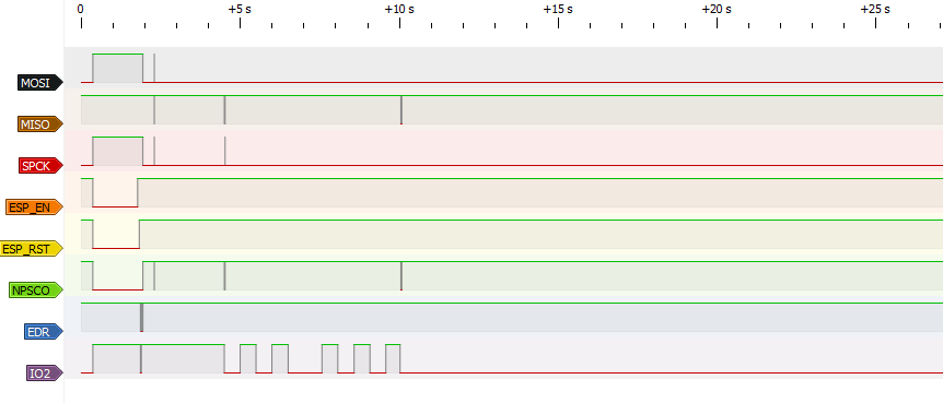
I've now reworked all the pads on the ESP, U12, and U1 parts.I have connected some of the data lines up to our signal analyser using the COMMS_ALT_HEADER on the back of the PCB.
Serial RX and TX work fine as known and I can see data being sent over during a firmware flash and regular ACKs coming back.
Below is a trace with the Duet going from running and being reset via the reset button on the PCB. All lines transistion at some point.
Happy to capture other lines or at other points - let me know.I have now had a small moment of working. It only lasted a few seconds. At start up, I polled with M122 to check the status (I'm using this to monitor if the MCU can talk to the ESP). It showed a normal response. I ran the M122 command again and it was back to failing. I hadn't made any changes and can't recreate it.
ESP Data Capture:
Duet ESP Close Up:
-
Hi all,
Can I assume that there are no further suggestions on this one?
I'm out of the office for the next week so there might be a delay in any responses from me.
Thanks, -
I think your logic analyser traces are not showing the full story. MOSI, MISO and SCLK bursts should always occur together, whenever NPCS0 goes low.
It's worth uploading the WiFi firmware again. I have observed that sometimes uploading the WiFi firmware appears to succeed but the firmware doesn't work properly. Uploading it again fixed the problem.
-
@dc42 As previous in the thread the firmware has been flashed many times and I've watched the data transfer over the logic analyser.
Update to this: we have replaced the flip flop next to the ESP module - U12 (HC74). This appears to have resolved the problem.
Looking at the schematic it appears to be some sort of tranfer initiate buffer. I didn't look at the SAM_TFR_RDY line or the output from U12 in to GPIO4 of the ESP which I assume will not have been changing and hence not starting the transfer(?).
@dc42 would you be able to give a quick explaination on the purpose of this part for completeness of this thread?
Thank you everyone for your help on this.
-
@maeterlinck said in Wifi Module Issue - Failed to get Wifi Status:
Update to this: we have replaced the flip flop next to the ESP module - U12 (HC74). This appears to have resolved the problem.
I'm glad you solved it - although I am surprised that the 74HC74 failed. I guess there is always a first time.
The reason for the 74HC74 is that when we designed the Duet WiFi, documentation for the ESP8266 was almost non-existent. In particular, there was no information on whether the chip supported edge-triggered interrupts, or how to program them. So the purpose of the 74HC74 is that after the Duet main processor signals to the WiFi module that it is ready for a data transfer, once the transfer has started then that request is removed, to guard against another transfer being initiated before the main processor is ready for a new one.
I'll mark this as solved.