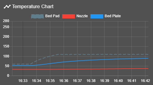
Dual thermistor setup for RRF3
-
Hello guys,
I 'm in the middle of upgrading my duet 2 wifi to rrf3.
Think most of the conversion is done, but I struggle a bit with my dual thermistor setup.
I've got silicon heater mat with its thermistor and I got a second thermistor drilled into the heatbed itself.For the rrf2 I got a dual thermistor setup working. So that the silicon mat could go to max 130 celsius if the bed temp isnt reached yet. This allowed for faster heating. But now I cant get it working. The "virtual" sensor for controling the silicon heater doesnt work. It doesnt shutdown when the max temp is reached. It just stops when the heatbed thermistor has reached the limit.
Maybe someone could help me. This was the code in rrf2:
;DUAL THERMISTOR SETUP
M305 S"Printbed" P0 X0 R4700 T100000 B4276
M307 H0 B0 S1                    ; PWM (B1 = bang-bang)
M305 S"Heatmat" P103 X3 R4700 T100000 B3950
M143 P100 H0 X103 A2 C0 S123            ; supervise silicone heater stays below 123°C
M143 P101 H0 X103 A1 C0 S130            ; supervise silicone heater shutdown at 130°C
M143 H0 S115                    ; maximum heatbed temperature
and this is what I got so far for rff3
;DUAL THERMISTOR SETUP for bed ;Bed M308 S0 P"bedtemp" Y"thermistor" R4700 T100000 B4276 ;Heatmat M308 S1 P"exp.thermistor3" Y"thermistor" R4700 T100000 B3950 M950 H0 C"bedheat" T0 M143 P1 H0 X1 A2 C0 S123 ; supervise silicone heater stays below 123°C M143 P1 H0 X1 A1 C0 S130 ; supervise silicone heater shutdown at 130°C M143 H0 S120 ; maximum heatbed temperature M140 H0 -
I just can't get that working on rrf3. Tried different options for few hours but heater does ignore the M143 commands.
Why isnt this working in rrf3? I really dont want to get back to the "old" slow heating method. -
Your M143 commands are wrong for RRF3.1. See https://duet3d.dozuki.com/Wiki/Gcode#Section_M143_in_RRF_3_01RC2_and_later.
-
I already tried to alter them and get rid of the X commands, but still doesnt work:
;DUAL THERMISTOR SETUP for bed
M308 S0 P"exp.thermistor3" Y"thermistor" T100000 B3950 A"Bed Pad"   ; configure sensor 0 as thermistor on pin bedtemp (pad sensor)
M308 S2 P"bedtemp" Y"thermistor" T100000 B3950 A"Bed Plate"  ; configure sensor 2 as thermistor on pin e1temp (plate sensor)
M950 H0 C"bedheat" T2 Q10                                   ; create bed heater output on out0 and map it to sensor 2 (plate sensor). Set PWM frequency to 10Hz
M143 H0 P100 T0 A2 S40                                  ; Regulate(A2) bed heater (H0) to have pad sensor below 110°C. Use Heater monitor 100 for it
M143 H0 P101 T0 A1 S50                                  ; Shut off (A1) bed heater (H0) if pad sensor exceeds 120°C. Use Heater monitor 101 for it
M143 H0 S120                                                ; Set bed heater max temperature to 120°C
M140 H0                                                  ; Mark heater H0 as bed heater (for DWC)
Can you tell me where exactly is the fault?
What I dont really get what the P parameter means. What is a heater monitor? I have to admit that the documentation is very cryptic for the whole new rrf3 stuff.
I also tried other parameters like P0 or P1, but the M143 settings are completely being ignored no matter what I do. I even changed the order of the commands and deleted the M143 H0 S120 command. -
Your M143 P parameters are out of range. From the link I sent you:
Each heater supports a certain number (3 in most builds of RRF) of monitors for that heater. The P parameter allows you to choose which monitor to configure.
By default, monitor 0 is set up to generate a heater fault if a temperature limit is exceeded, and monitors 1 and 2 are disabled.
Had you run M98 P"config.g" to check for errors in config.g, you would probably have known this from the error messages.
-
I already tried other P values like 0 or 1. But it doesnt change a thing, the current config check response is this:
M98 P"config.g"
RepRap name: My Duet
TELNET is disabled
Warning: Heater 1 appears to be over-powered. If left on at full power, its temperature is predicted to reach 651C
And this is the current code:
;DUAL THERMISTOR SETUP for bed M308 S0 P"exp.thermistor3" Y"thermistor" T100000 B3950 A"Bed Pad" ; configure sensor 0 as thermistor on pin bedtemp (pad sensor) M308 S2 P"bedtemp" Y"thermistor" T100000 B3950 A"Bed Plate" ; configure sensor 2 as thermistor on pin e1temp (plate sensor) M950 H0 C"bedheat" T2 Q10 ; create bed heater output on out0 and map it to sensor 2 (plate sensor). Set PWM frequency to 10Hz M143 H0 P0 T0 A2 S40 ; Regulate(A2) bed heater (H0) to have pad sensor below 110°C. Use Heater monitor 100 for it M143 H0 P0 T0 A1 S50 ; Shut off (A1) bed heater (H0) if pad sensor exceeds 120°C. Use Heater monitor 101 for it M143 H0 S120 ; Set bed heater max temperature to 120°C M140 H0 ; Mark heater H0 as bed heater (for DWC) -
Hi Mugga,
I use the same configuration as you.
For me the following code work fine (based on your inspiration):
M308 S0 P"bedtemp" Y"thermistor" A"Bed Pad" T100000 B3950  ; configure sensor 0 as thermistor on pin bedtemp
M308 S4 P"e2temp" Y"thermistor" A"Bed Plate" T98801 B4185  ; configure sensor 4 as thermistor on pin e0temp
M950 H0 C"bedheat" T4                                      ; create bed heater output on bedheat and map it to sensor 4
M140 H0                                                    ; map heated bed to heater 0
M143 H0 P0 T0 A2 S110 C0                                   ; Regulate (A2) bed heater (H0) to have pad sensor below 110°C. Use Heater monitor P0 for it
M143 H0 P1 T0 A0 S120 C0                                   ; Shut off (A1) bed heater (H0) if pad sensor exceeds 120°C.    Use Heater monitor P1 for it
M307 H0 B0 S1.00                                           ; disable bang-bang mode for the bed heater and set PWM limit