Duet WIFI & Precision Piezo sensor configuration (BLV printer)
-
Hello !
I have build the BLV 3D-printer and I am working at a new design to use the precisionpiezo v2.0 with a 2-1 Mellow hotend (mosquito clone).The design is now in prototype, ready to test.
BUT: I am trying to config the reprap firmware with the PIEZO sensor.
In the configurator I see a PIEZO selection, but I can't select it.
How must the sensor be configured in the right way?
I have used some examples, I get readings (z) when I touch the heatend, so that looks ok.When I do a Z-home, it works nice. The sensor stops the bed.
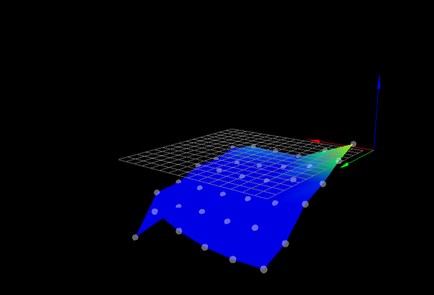
When I do a Mesh compensation, it works too, and I get a result:
height map min error -1.038, max error 0.095, mean -0.439, deviation 0.244
The image of it below, looks weird, the heated bed seems to be very flat, needs some bedleveling but it's not that bad...I have this configuration now:
M557 X40:320 Y40:320 S50 ; define mesh gridZ-Probe
M558 P1 C"!zprobe.in" R0.8 F300 Z1
G31 P500 X0 Y0 Z0Z-probe in the DASHBOARD shows 491 when the bed is lowered (nozzle not touching bed).
I use:
Board: Duet 2 WiFi (2WiFi)
Firmware: RepRapFirmware for Duet 2 WiFi/Ethernet 3.1.1 (2020-05-19b2)
Duet WiFi Server Version: 1.23Any help would be nice.
With kind regards,
Arthur
-
this looks like you have not adjusted the bed with the leveling screws.
do the paper adjustment for all 4 corners and then run a mesh bed leveling
-
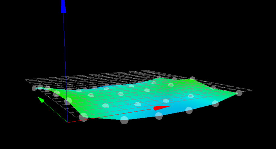
I have leveled the bed now, re-run a True Bed-leveling (G32) which gives these heightmap:
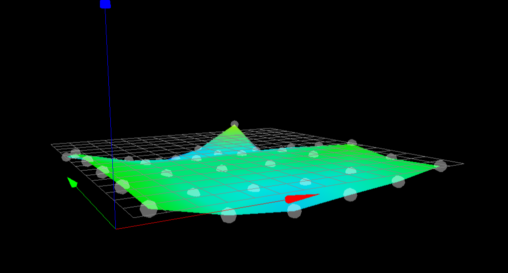
36 points probed, min error -0.305, max error 0.080, mean -0.083, deviation 0.071After that, I started the MESH (G29) compensation:
Results: 36 points probed, min error -0.270, max error 0.020, mean -0.102, deviation 0.069
So, what do you think about this ?
") Arthur
Arthur -
Are you homing the Z axis with the probe in the center of the bed?
That doesn't look too bad, really. I would try a G29 with a denser mesh to see how it really looks in detail.
The real test will be trying to print something like a test pattern once without G29 and once with G29 enabled to see the difference.
-
For physically levelling the bed I find it useful to probe only five points, the four corners and the centre.
The pattern you are seeing there may be the result of the bed moving different amounts at different points when the nozzle touches it, The best way to improve that is to increase the sensitivity of the Orion.
Idris
-
@Moriquendi Ok, how must I increase the sensivity ?
And what are the right settings, check my question at the start of this post.
Arthur -
Reduce the P value in your G31 statement so that it is closer to the resting z-probe value (491).
You may need to experiment with how tight the four assembly screws are, if they're too tight the probe will be less sensitive.
To avoid false triggers reduce acceleration and jerk during probing.
Idris