First Post & few Questions (Low+High Endstop & Blobs Issue)
-
Hello everybody,
this is my first post.(Please excuse my bad english it's not my native language)
I've been printing for 8 years now, but with the first M3D Micro beta printer that came out in 2012, but now it is to small for me (10x10). Now I have built a bigger cartaisan printer on my own.
I have learned a lot out of this forum and found a lot of solutions while reading.But now I'm stuck at a few points.
First of all:
Thanks to @deckingman who inspired me to build a multicolor printer by reading his blog.
Of cours also thanks to @DC42 for his help and solutions in this forum.
I'm really glad to be a member in this communitySo here is my setup:
- Cartaisan Printer
- Duet Wifi v1.04 + Duex
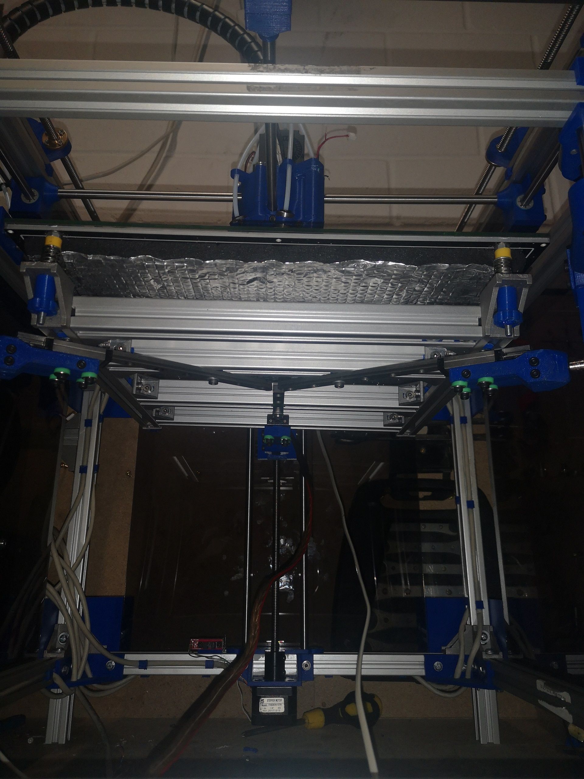
- Dual X and Dual Y and Tripple Z axes
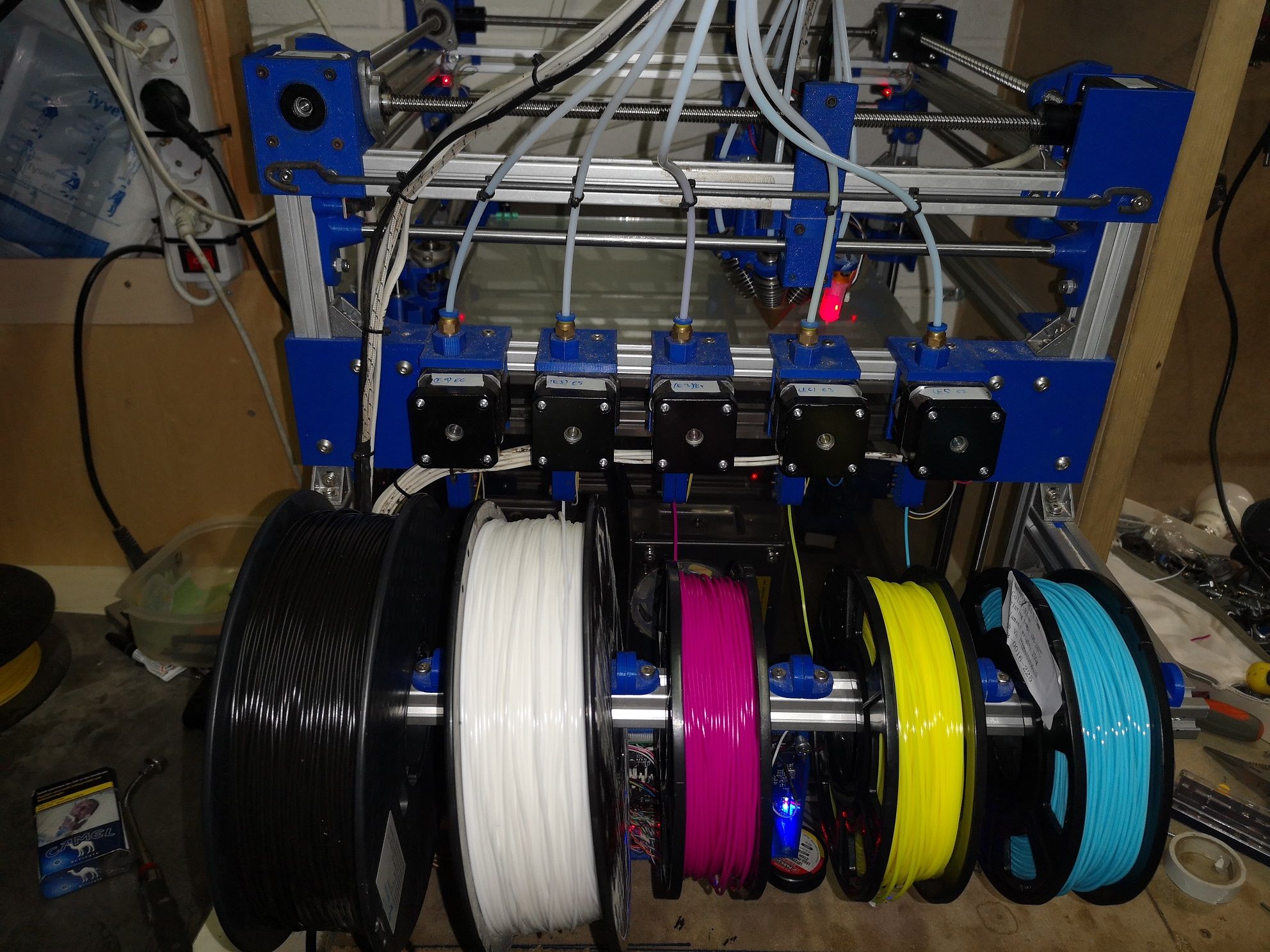
- 5 extruders (Magenta, Yellow, Cyan, White, Black)
- 12 stepper motors NEMA 17 (max 1500ma)(10 on Duet+Duex+2 external)
- Diamond Hotend 5 in 1
- 5 Bowden tubes (80cm)
- 30 x 30 cm Printbed
- 7 optical Endstops + BLTouch
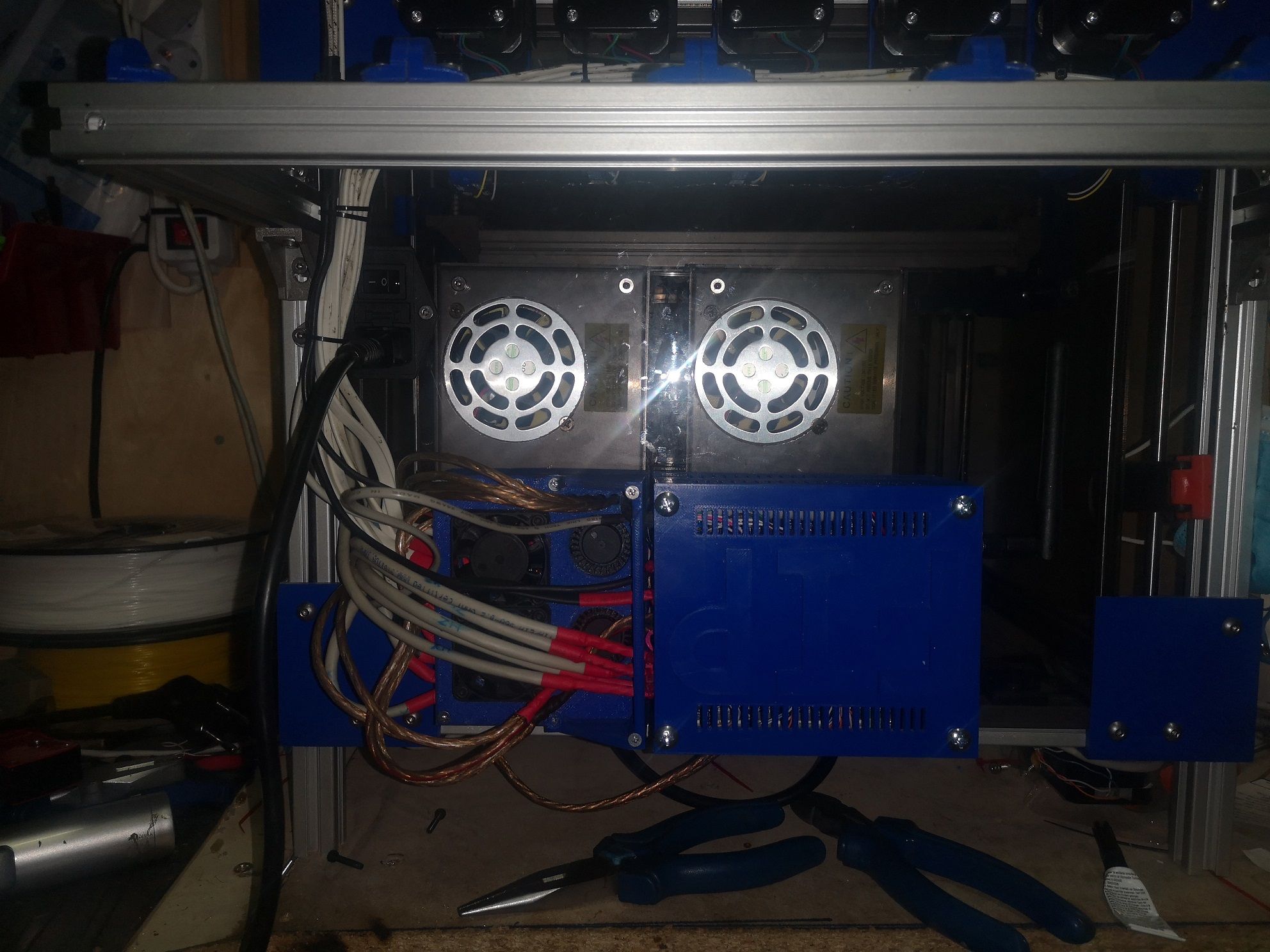
- 2x Vin @ 24Volt and 600Watt (1. Duet+Duexan 2. Printbed via Mosfet)
- 2 Fan + 5 Blower (External Driver, Mosfet, 2 Duet+Duex, 2 Diamondcarriage an 1 Partcooler)
- 5 Activ High switches as filamentsensor*
- 5 temperature sensors ( Hotend, Printbed, Duet, Mosfet & External Driver)
- actually there are 17 Tools set
- RRF 3.1.1.
(* It didn't work well, the printer kept restarting at the beginning of a print, so i deactivated them. Too much noise interferences. I will replace them with other sensors)
I think that's it.
I designed this printer by myself on Solidworks, so all parts are custom made an printed with a small printer( a gift,chinese brand: Singma but it had done his job good) Some parts will be reprinted like the Duethousing with this big printer. The one i used just had a printarea of 13x13 cm.
I tried to build a Printer which isn't too big bud also have a big printarea. So i tried to set it as compact as possible. The outer dimensions are 44x44 cm and the printarea is 30x30 cm. The filamentspool are mounted outside on the left handside.
I've already done some prints an a lot of tests. The instructions an the forum helped a lot, so that it wasn't that hard.
Now my issues:
-
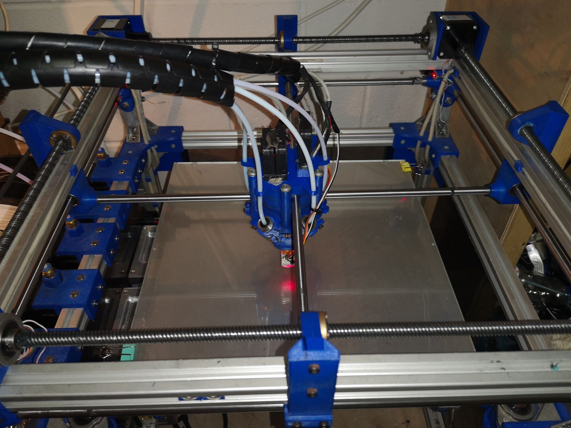
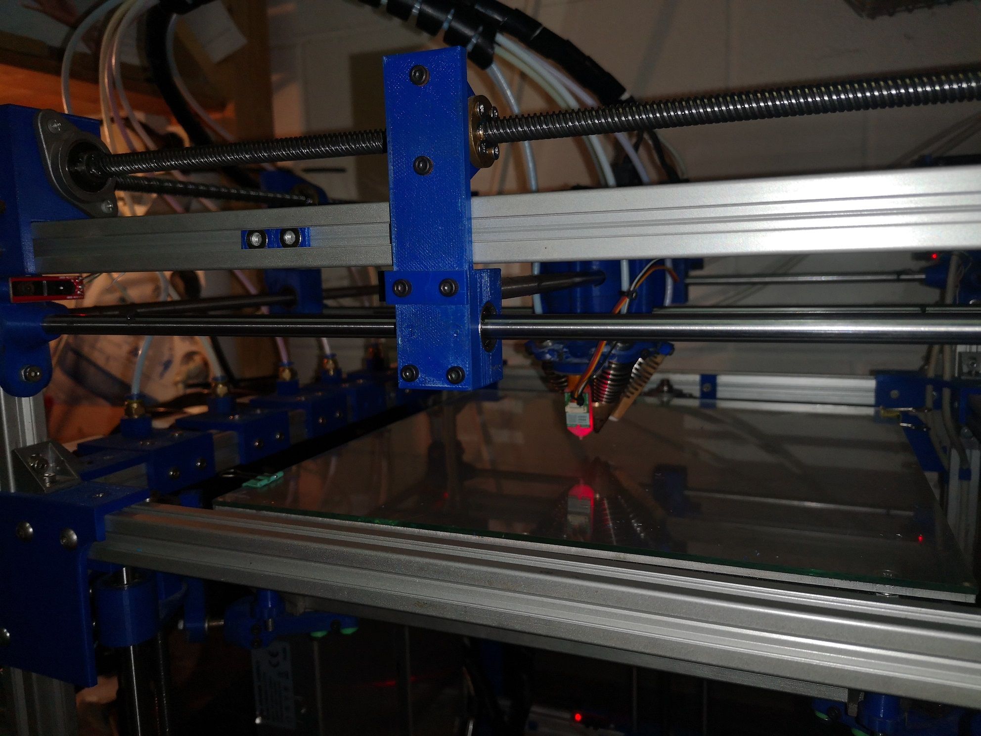
I got a dual X and dual Y setup, it also works very well. But it just uses one endstop switch. it worked good at the beginning, but as i speed up the speed of the axis i got some issues. The carrier stuck on Y axis and the Printhead didn't move or just a bit in that direction.
The reason i speed up the speed was that i tought that it will be usefull to evitate blobs at the beginning of a layer. (At the beginning it was lower and worked very good)
I already set Firmware retraction (8 mm) an pressure advance (0.8) but the blobs never fully disapeared. But it was already better.
I could set down the speed, but then the blobs will become bigger.
I think the longer the hotend stays over the beginning of a layer, the worser the blobs get.
By the way, I use the prusa slicer, it can run 17 tools without crashing.
Slic3er crashed all the time. I also modified Cura to have 18 tools but it get very slow and i couldn't see every icon on the screen, that's why i'm using PrusaSlicer. There I enabled also Firmware retraction (all 5 filaments are beeing retracted) -
My question is:
How can I set two endstops at each end of the axis? (High and low)
Ass you can see on the pictures, my dual Axis setup is mirrored*.
I want him to go to one end and after i want him to go to the other end.
I think then it will be fully synchronised and wont stuck anymore.
(*Saved place to keep the printe compact)
- And if I have to set down the speed, how could i evitate these blobs?
Here is my actual configuration (shortened):
; Driver mapping M584 X1:2 Y10:11 Z0:3:4 U2 V11 W3 A4 E5:6:7:8:9 P3 ; set drive mapping M671 X150:-25:325 Y325:-25:-25 S1 ; leadscrews at rear middle, front left and front right ; Drives M569 P2 S0 ; physical drive 2 goes forwards M569 P0 S1 ; physical drive 0 goes forwards M569 P1 S1 ; physical drive 1 goes forwards M569 P3 S1 ; physical drive 3 goes forwards M569 P4 S1 ; physical drive 4 goes forwards M569 P5 S0 ; physical drive 5 goes forwards M569 P6 S0 ; physical drive 6 goes forwards M569 P7 S0 ; physical drive 7 goes forwards M569 P8 S0 ; physical drive 8 goes forwards M569 P9 S0 ; physical drive 9 goes forwards M569 P10 S0 ; physical drive 10 goes forwards M569 P11 S1 ; physical drive 11 goes forwards M350 X16 Y16 Z16 E16:16:16:16:16 I1 ; configure microstepping with interpolation M92 X400.00 Y400.00 Z2133.33 E85.6:85.6:85.6:85.6:85.6 ; set steps per mm M566 X2000.00 Y2000.00 Z100.00 E2000.00:2000.00:2000.00:2000.00:2000.00 ; set maximum instantaneous speed changes (mm/min) M203 X6000.00 Y6000.00 Z900.00 E4000.00:4000.00:4000.00:4000.00:40000.00 ; set maximum speeds (mm/min) M201 X5000.00 Y5000.00 Z100.00 E2500.00:2500.00:2500.00:2500.00:2500.00 ; set accelerations (mm/s^2) M906 X1000 Y1000 Z1000 E1000:1000:1000:1000:1000 I80 ; set motor currents (mA) and motor idle factor in per cent M84 S30 ; Set idle timeout ; Axis Limits M208 X0 Y0 Z0 U0 V0 W0 A0 S1 ; set axis minima M208 X300 Y300 Z270 U300 V300 W270 A270 S0 ; set axis maxima ; Endstops M584 X1:2 Y10:11 Z0:3:4 U2 V11 W3 A4 E5:6:7:8:9 ; M574 X2 S1 P"ystop" ; configure sensorless endstop for low end on X M574 Y2 S1 P"connlcd.encb" ; configure sensorless endstop for low end on Y M574 Z1 S1 P"xstop+e0stop+e1stop" ; configure sensorless endstop for low end on Z M574 U1 S1 P"zstop" ; M574 V1 S1 P"connlcd.enca" ; ; Z-Probe M950 S0 C"duex.pwm5" ; create servo pin 0 for BLTouch M558 P9 C"^zprobe.in" H5 F120 T6000 ; set Z probe type to bltouch and the dive height + speeds G31 P500 X0 Y-35 Z1.8 ; set Z probe trigger value, offset and trigger height M557 X35:265 Y35:265 S230 ; define mesh grid M563 P0 S"Black" D0:1:2:3:4 H1 ; define tool 4 G10 P0 X0 Y0 Z0 ; set tool 4 axis offsets G10 P0 R200 S200 ; set initial tool 4 active and standby temperatures to 0C M568 P0 S1 ; enable mixing for tool 4 M567 P0 E0.025:0.025:0.025:0.025:0.9 ; set mixing ratios for tool 4 M563 P1 S"White" D0:1:2:3:4 H1 ; define tool 4 G10 P1 X0 Y0 Z0 ; set tool 4 axis offsets G10 P1 R200 S200 ; set initial tool 4 active and standby temperatures to 0C M568 P1 S1 ; enable mixing for tool 4 M567 P1 E0.025:0.025:0.025:0.9:0.025 ; set mixing ratios for tool 4 M563 P2 S"Light Grey" D0:1:2:3:4 H1 ; define tool 4 G10 P2 X0 Y0 Z0 ; set tool 4 axis offsets G10 P2 R200 S200 ; set initial tool 4 active and standby temperatures to 0C M568 P2 S1 ; enable mixing for tool 4 M567 P2 E0.034:0.033:0.033:0.675:0.225 ; set mixing ratios for tool 4 M563 P3 S"Grey" D0:1:2:3:4 H1 ; define tool 4 G10 P3 X0 Y0 Z0 ; set tool 4 axis offsets G10 P3 R200 S200 ; set initial tool 4 active and standby temperatures to 0C M568 P3 S1 ; enable mixing for tool 4 M567 P3 E0.034:0.033:0.033:0.45:0.45 ; set mixing ratios for tool 4 M563 P4 S"Dark Grey" D0:1:2:3:4 H1 ; define tool 0 G10 P4 X0 Y0 Z0 ; set tool 0 axis offsets G10 P4 R200 S200 ; set initial tool 0 active and standby temperatures to 0C M568 P4 S1 ; enable mixing for tool 0 M567 P4 E0.034:0.033:0.033:0.225:0.675 ; set mixing ratios for tool 0 M563 P5 S"Cyan" D0:1:2:3:4 H1 ; define tool 13 G10 P5 X0 Y0 Z0 ; set tool 13 axis offsets G10 P5 R200 S200 ; set initial tool 13 active and standby temperatures to 0C M568 P5 S1 ; enable mixing for tool 13 M567 P5 E0.9:0.025:0.025:0.025:0.025 ; set mixing ratios for tool 13 M563 P6 S"Light Blue" D0:1:2:3:4 H1 ; define tool 12 G10 P6 X0 Y0 Z0 ; set tool 12 axis offsets G10 P6 R200 S200 ; set initial tool 12 active and standby temperatures to 0C M568 P6 S1 ; enable mixing for tool 12 M567 P6 E0.675:0.034:0.225:0.033:0.033 ; set mixing ratios for tool 12 M563 P7 S"Blue" D0:1:2:3:4 H1 ; define tool 7 G10 P7 X0 Y0 Z0 ; set tool 7 axis offsets G10 P7 R200 S200 ; set initial tool 7 active and standby temperatures to 0C M568 P7 S1 ; enable mixing for tool 7 M567 P7 E0.45:0.034:0.45:0.033:0.033 ; set mixing ratios for tool 7 M563 P8 S"Purple" D0:1:2:3:4 H1 ; define tool 11 G10 P8 X0 Y0 Z0 ; set tool 11 axis offsets G10 P8 R200 S200 ; set initial tool 11 active and standby temperatures to 0C M568 P8 S1 ; enable mixing for tool 11 M567 P8 E0.225:0.034:0.675:0.033:0.033 ; set mixing ratios for tool 11 M563 P9 S"Magenta" D0:1:2:3:4 H1 ; define tool 2 G10 P9 X0 Y0 Z0 ; set tool 2 axis offsets G10 P9 R200 S200 ; set initial tool 2 active and standby temperatures to 0C M568 P9 S1 ; enable mixing for tool 2 M567 P9 E0.025:0.025:0.9:0.025:0.025 ; set mixing ratios for tool 2 M563 P10 S"Hot Pink" D0:1:2:3:4 H1 ; define tool 10 G10 P10 X0 Y0 Z0 ; set tool 10 axis offsets G10 P10 R200 S200 ; set initial tool 10 active and standby temperatures to 0C M568 P10 S1 ; enable mixing for tool 10 M567 P10 E0.034:0.225:0.675:0.033:0.033 ; set mixing ratios for tool 10 M563 P11 S"Red" D0:1:2:3:4 H1 ; define tool 6 G10 P11 X0 Y0 Z0 ; set tool 6 axis offsets G10 P11 R200 S200 ; set initial tool 6 active and standby temperatures to 0C M568 P11 S1 ; enable mixing for tool 6 M567 P11 E0.034:0.45:0.45:0.033:0.033 ; set mixing ratios for tool 6 M563 P12 S"Orange" D0:1:2:3:4 H1 ; define tool 9 G10 P12 X0 Y0 Z0 ; set tool 9 axis offsets G10 P12 R200 S200 ; set initial tool 9 active and standby temperatures to 0C M568 P12 S1 ; enable mixing for tool 9 M567 P12 E0.034:0.675:0.225:0.033:0.033 ; set mixing ratios for tool 9 M563 P13 S"Yellow" D0:1:2:3:4 H1 ; define tool 1 G10 P13 X0 Y0 Z0 ; set tool 1 axis offsets G10 P13 R200 S200 ; set initial tool 1 active and standby temperatures to 0C M568 P13 S1 ; enable mixing for tool 1 M567 P13 E0.025:0.9:0.025:0.025:0.025 ; set mixing ratios for tool 1 M563 P14 S"Lime" D0:1:2:3:4 H1 ; define tool 14 G10 P14 X0 Y0 Z0 ; set tool 14 axis offsets G10 P14 R200 S200 ; set initial tool 14 active and standby temperatures to 0C M568 P14 S1 ; enable mixing for tool 14 M567 P14 E0.225:0.675:0.034:0.033:0.033 ; set mixing ratios for tool 14 M563 P15 S"Green" D0:1:2:3:4 H1 ; define tool 5 G10 P15 X0 Y0 Z0 ; set tool 5 axis offsets G10 P15 R200 S200 ; set initial tool 5 active and standby temperatures to 0C M568 P15 S1 ; enable mixing for tool 5 M567 P15 E0.45:0.45:0.034:0.033:0.033 ; set mixing ratios for tool 5 M563 P16 S"Spring Green" D0:1:2:3:4 H1 ; define tool 13 G10 P16 X0 Y0 Z0 ; set tool 13 axis offsets G10 P16 R200 S200 ; set initial tool 13 active and standby temperatures to 0C M568 P16 S1 ; enable mixing for tool 13 M567 P16 E0.675:0.225:0.034:0.033:0.033 ; set mixing ratios for tool 13 M207 S8 F4000 ;set firmware retraction ; Sets filament diameter for all extruders, which also enables volumetric printing M572 D0:1:2:3:4 S0.8 ; M200 D1.75 ; set all extruder filament diameters to 1.75mmAnd here a few pictures:
( Some of theme are old ones)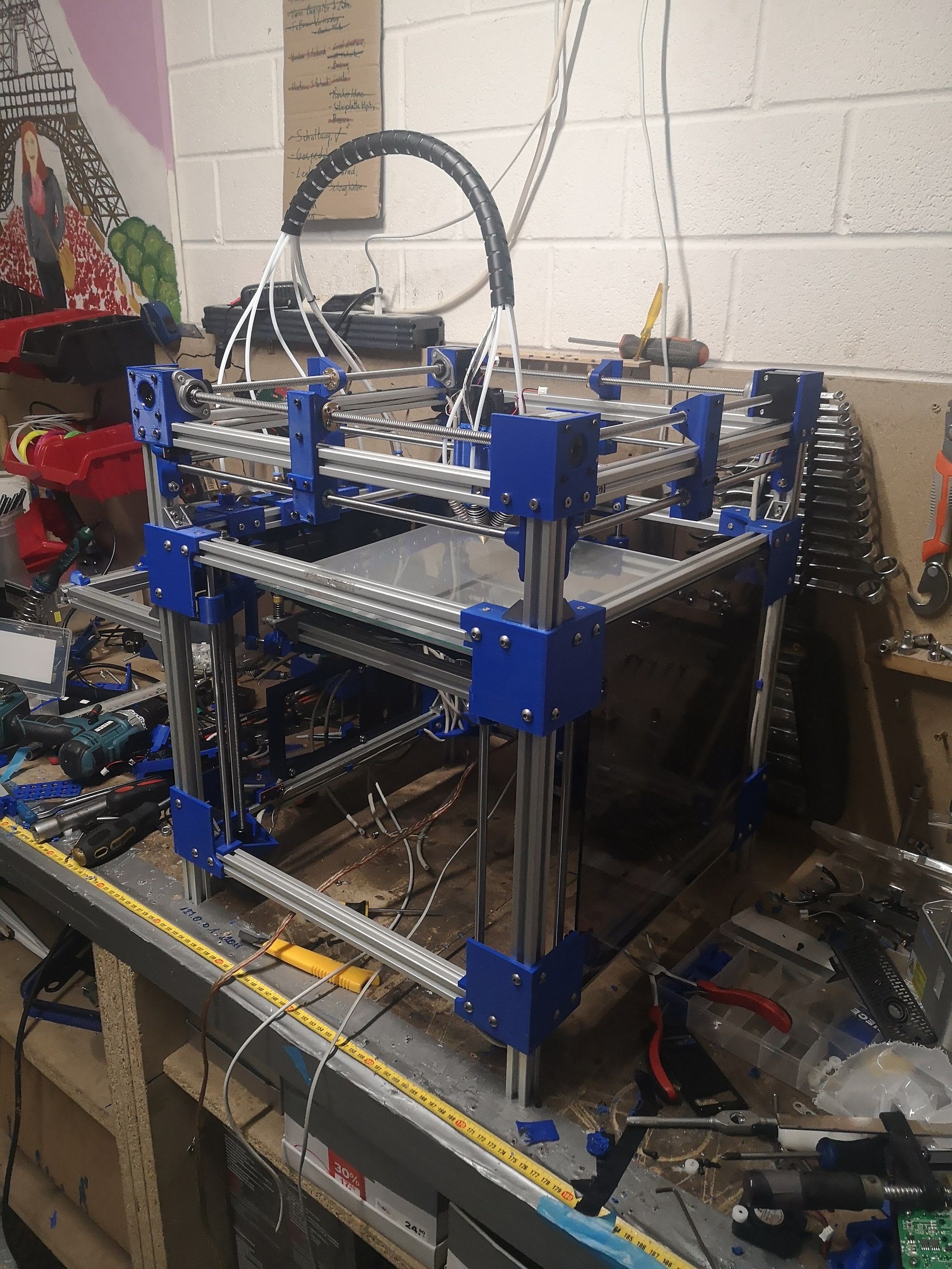
Here are some of my prints i've already done for testing; ther you can also see the blobs and the progress of getting rid of them.
In some Picture you can see that one colour didn't extrudet but i fixed it.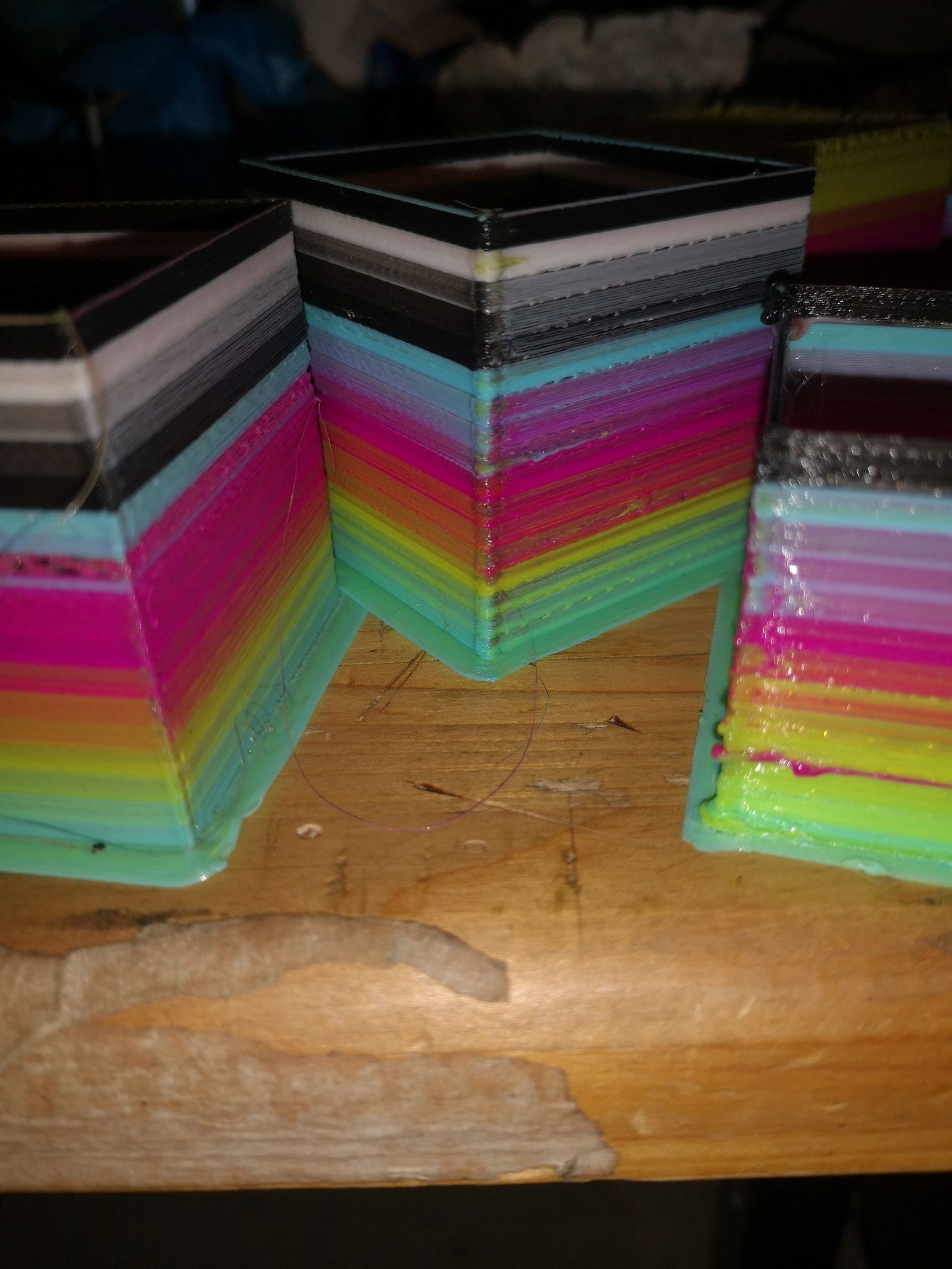
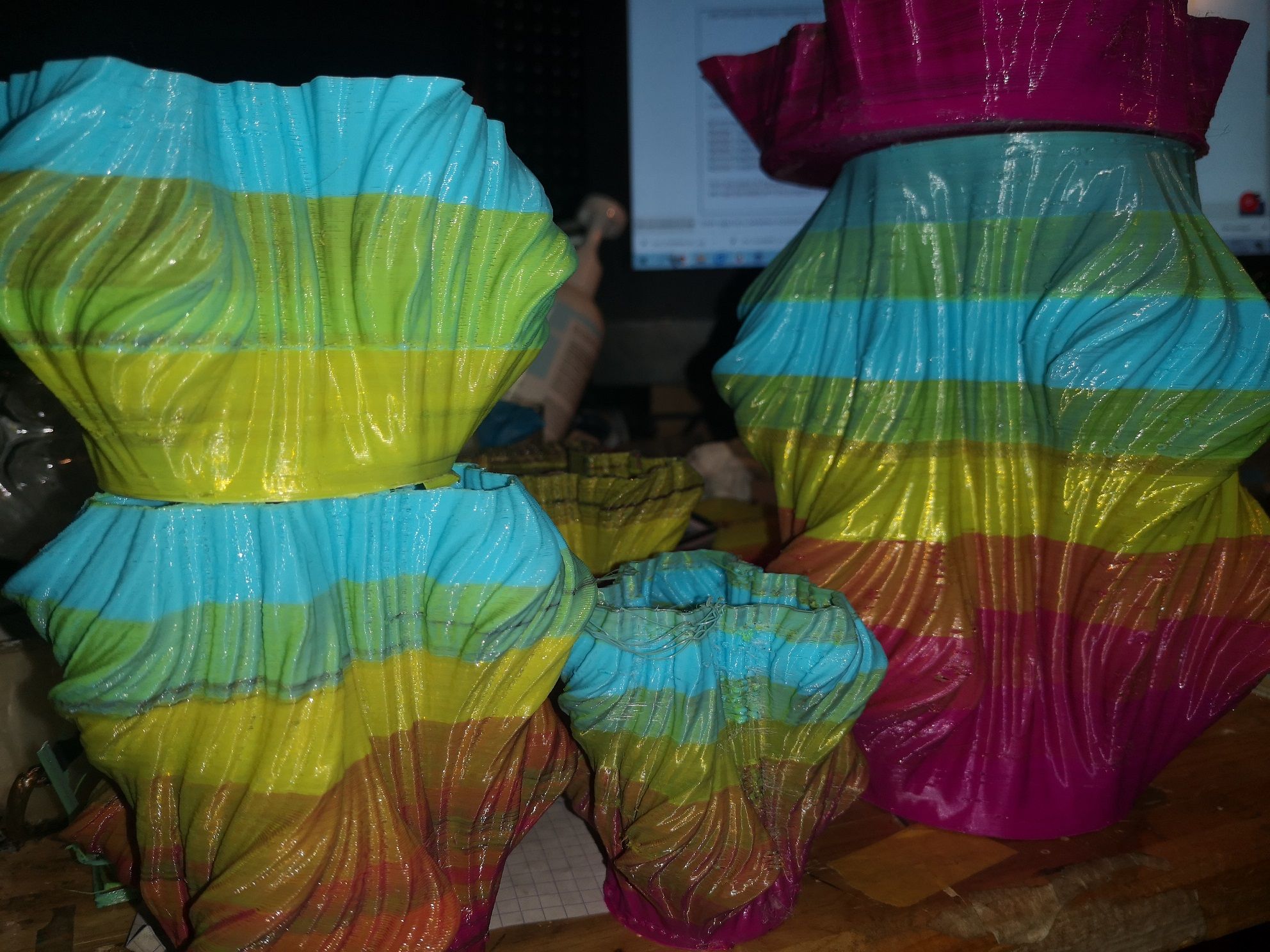
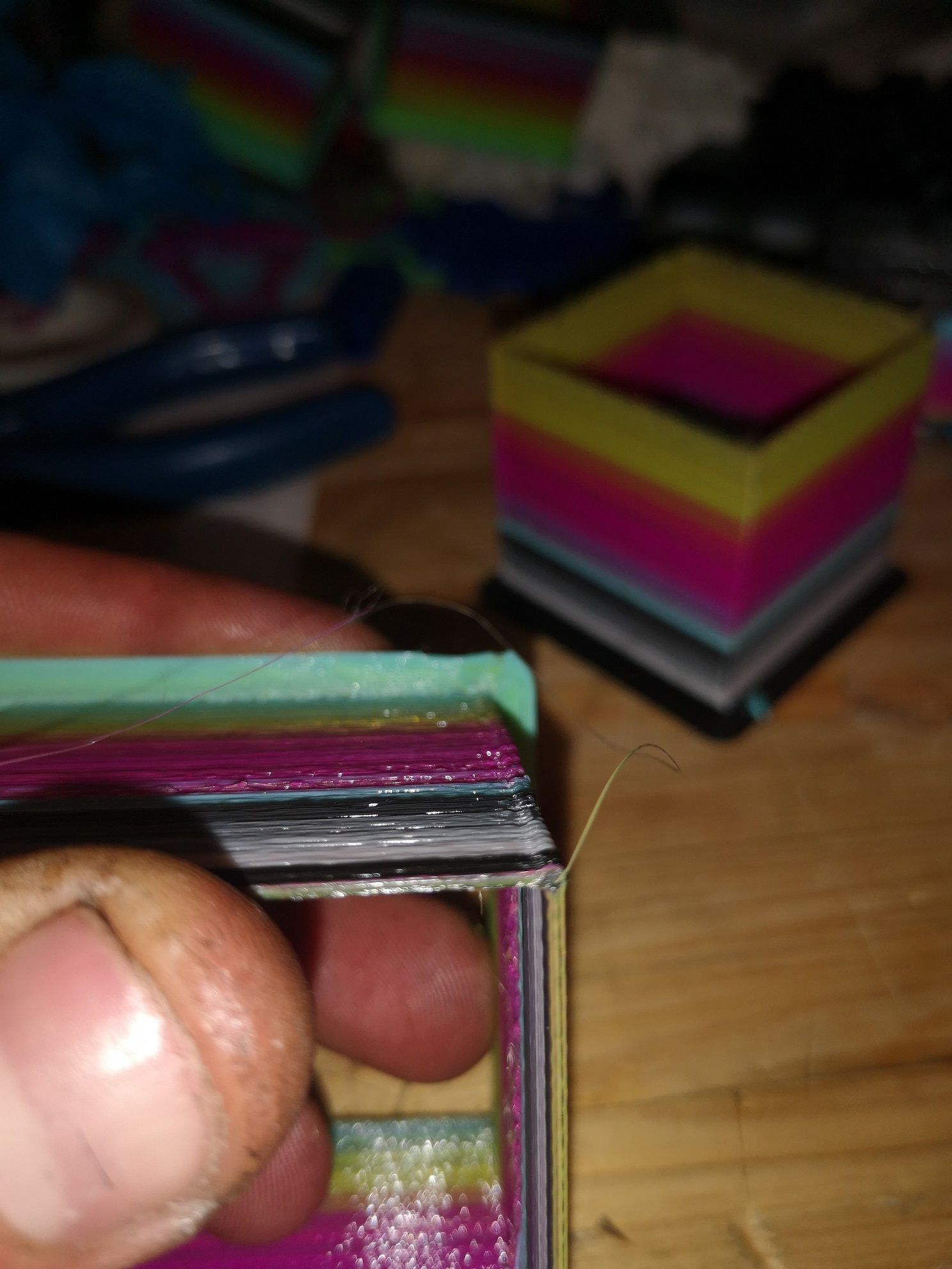
yhis ist the best resultate i get.
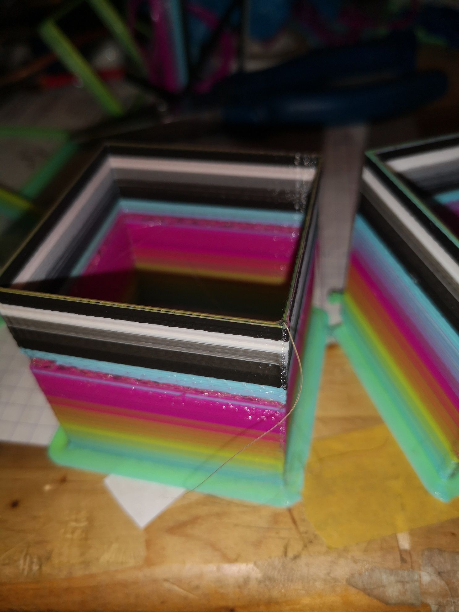
maybe someone has an solution for my problem
thanks in advance
FITT
-
@FITT said in First Post & few Questions (Low+High Endstop & Blobs Issue):
E85.6:85.6:85.6:85.6:85.6
what kind of extruder are they? maybe switching to dual geared extruders could help
what is your reason for wanting to use high and low endstops?
on the duet endstops are not taken into account during normal moves. the software movement limits of the duet should take care of this.
otherwise you can reconfigure the endstops on the fly if neededi am not sure if leadscrews in a vertical position are working.
check out this project for a beltless hypercube. https://www.thingiverse.com/thing:2929869
he is using this
https://www.igus.de/product/813
and
https://www.igus.de/product/895
for a zero backlash setupalso i dont see your thermistor setup
-
Hello Veti,
this are direct driven extruder from an old printer. I took it from 5 old printers where the printbed was srewed (a dobot replica,singma XGM-5a: https://item.jd.com/32249923157.html)
I reused the steppermotors and the extrudermechanism. The other parts are from doltmechatronik.de and reprap.me.
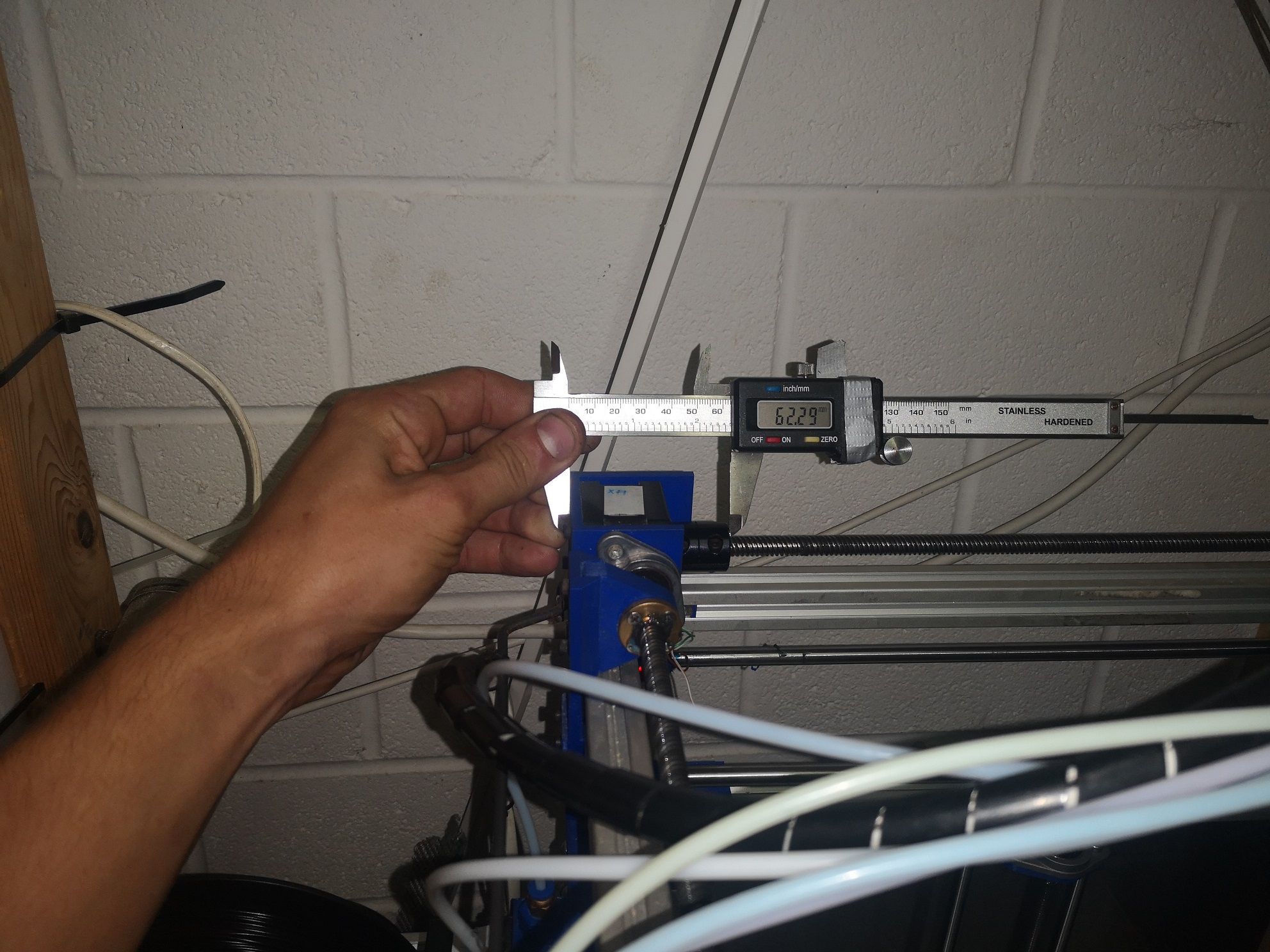
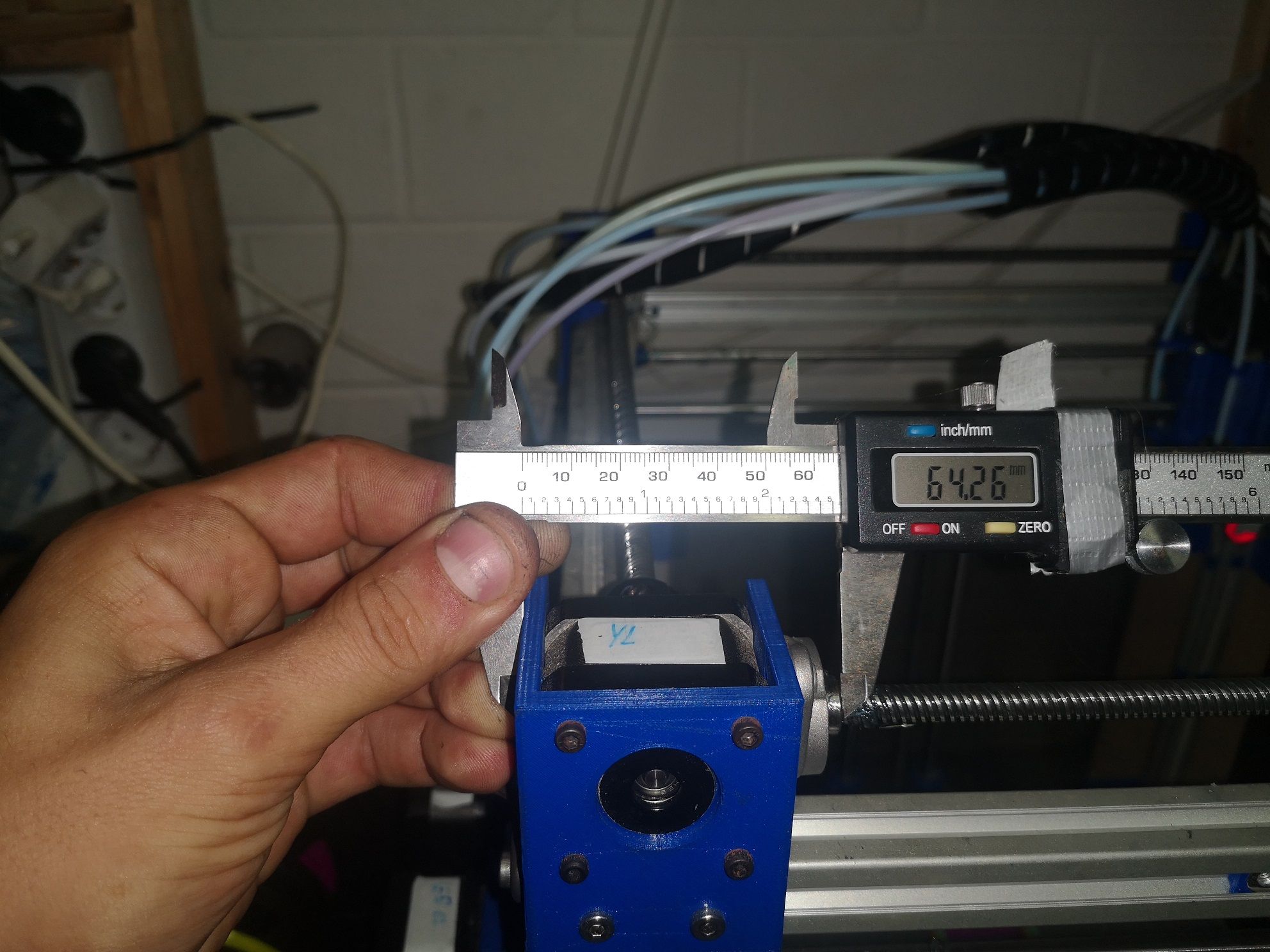
E85.6:85.6:85.6:85.6:85.6 is a weird number, but i callibrated the exdruder like that and it worked fine.The reason i want to use high and low endstops is, that i want the printer to synchronise during homing not while printing. I can adjust it manualy but that is not my goal. There is a diffrence of 2 mm at the end of one leadscrew and at the beginning of the other.
I also already tried to rewrite the homeall.gcode, but it never triggered the second endstop. Now it just uses one an then stops.
It also works fine, but sometimes it blocks and the movement aren't parallel anymore.
Thanks for the tip of backlach, for now this isn't prior. But I'll change it in the future.
I've tried to put the endstops togeter at the M574 code but it didn't work.
You said that I could change the endstopbehaviour by the fly. So that means, I can put a remap after the first endstop is triggered in the home code?Here is a picture to explaine my idea:

At low speed it works good but at high it blocks sometimes.
I took out the thermistor setup because the post got over 20000 letters. I'll repost it.
I'll put it now here:0:/sys/config.g ; Configuration file for Duet WiFi (firmware version 3) ; executed by the firmware on start-up ; ; generated by RepRapFirmware Configuration Tool v3.1.4 on Wed Sep 09 2020 22:34:20 GMT+0200 (Mitteleuropäische Sommerzeit) ; General preferences G90 ; send absolute coordinates... M83 ; ...but relative extruder moves M550 P"FIP" ; set printer name M111 S1 ; G21 ; M555 P1 ; ; Network M552 S1 ; enable network M586 P0 S1 ; enable HTTP M586 P1 S0 ; disable FTP M586 P2 S0 ; disable Telnet ; Driver mapping M584 X1:2 Y10:11 Z0:3:4 U2 V11 W3 A4 E5:6:7:8:9 P3 ; set drive mapping M671 X150:-25:325 Y325:-25:-25 S1 ; leadscrews at rear middle, front left and front right ; Drives M569 P2 S0 ; physical drive 2 goes forwards M569 P0 S1 ; physical drive 0 goes forwards M569 P1 S1 ; physical drive 1 goes forwards M569 P3 S1 ; physical drive 3 goes forwards M569 P4 S1 ; physical drive 4 goes forwards M569 P5 S0 ; physical drive 5 goes forwards M569 P6 S0 ; physical drive 6 goes forwards M569 P7 S0 ; physical drive 7 goes forwards M569 P8 S0 ; physical drive 8 goes forwards M569 P9 S0 ; physical drive 9 goes forwards M569 P10 S0 ; physical drive 10 goes forwards M569 P11 S1 ; physical drive 11 goes forwards M350 X16 Y16 Z16 E16:16:16:16:16 I1 ; configure microstepping with interpolation M92 X400.00 Y400.00 Z2133.33 E85.6:85.6:85.6:85.6:85.6 ; set steps per mm M566 X2000.00 Y2000.00 Z100.00 E2000.00:2000.00:2000.00:2000.00:2000.00 ; set maximum instantaneous speed changes (mm/min) M203 X6000.00 Y6000.00 Z900.00 E4000.00:4000.00:4000.00:4000.00:40000.00 ; set maximum speeds (mm/min) M201 X5000.00 Y5000.00 Z100.00 E2500.00:2500.00:2500.00:2500.00:2500.00 ; set accelerations (mm/s^2) M906 X1000 Y1000 Z1000 E1000:1000:1000:1000:1000 I80 ; set motor currents (mA) and motor idle factor in per cent M84 S30 ; Set idle timeout ; Axis Limits M208 X0 Y0 Z0 U0 V0 W0 A0 S1 ; set axis minima M208 X300 Y300 Z270 U300 V300 W270 A270 S0 ; set axis maxima ; Endstops M584 X1:2 Y10:11 Z0:3:4 U2 V11 W3 A4 E5:6:7:8:9 ; M574 X2 S1 P"ystop" ; configure sensorless endstop for low end on X M574 Y2 S1 P"connlcd.encb" ; configure sensorless endstop for low end on Y M574 Z1 S1 P"xstop+e0stop+e1stop" ; configure sensorless endstop for low end on Z M574 U1 S1 P"zstop" ; M574 V1 S1 P"connlcd.enca" ; ; Z-Probe M950 S0 C"duex.pwm5" ; create servo pin 0 for BLTouch M558 P9 C"^zprobe.in" H5 F120 T6000 ; set Z probe type to bltouch and the dive height + speeds G31 P500 X0 Y-35 Z1.8 ; set Z probe trigger value, offset and trigger height M557 X35:265 Y35:265 S230 ; define mesh grid ; Heaters M308 S0 P"bedtemp" Y"thermistor" A"Printbett" T100000 B4138 ; configure sensor 0 as thermistor on pin bedtemp M950 H0 C"bed_heat" T0 ; create bed heater output on bedheat and map it to sensor 0 M307 H0 A26.7 C106.8 D2.4 S1.00 V23.8 B0 ; disable bang-bang mode for the bed heater and set PWM limit M140 H0 S65 R65 ; map heated bed to heater 0 M143 H0 S120 ; set temperature limit for heater 0 to 120C M308 S1 P"duex.e6temp" Y"thermistor" T100000 B4138 ; configure sensor 1 as thermistor on pin duex.e6temp M950 H1 C"duex.e2heat" T1 ; create nozzle heater output on duex.e2heat and map it to sensor 1 M307 H1 B0 S1.00 ; disable bang-bang mode for heater and set PWM limit M143 H1 S280 ; M308 S2 P"duex.e2temp" Y"thermistor" A"Mosfet" T100000 B4138 ; configure sensor 1 as thermistor on pin duex.e6temp M950 H2 C"duex.e2temp" T2 ; create nozzle heater output on duex.e2heat and map it to sensor 1 M307 H2 B0 S1.00 ; disable bang-bang mode for heater and set PWM limit M308 S3 P"duex.e3temp" Y"thermistor" A"Y-Driver" T100000 B4138 ; configure sensor 1 as thermistor on pin duex.e6temp M950 H3 C"duex.e3temp" T3 ; create nozzle heater output on duex.e2heat and map it to sensor 1 M307 H3 B0 S1.00 ; disable bang-bang mode for heater and set PWM limit M308 S4 P"duex.e4temp" Y"thermistor" A"Duet & Duex" T100000 B4138 ; configure sensor 1 as thermistor on pin duex.e6temp M950 H4 C"duex.e4temp" T4 ; create nozzle heater output on duex.e2heat and map it to sensor 1 M307 H4 B0 S1.00 ; disable bang-bang mode for heater and set PWM limit ; Fans M950 F0 C"duex.fan6" Q500 ; create fan 0 on pin duex.fan3 and set its frequency M106 P0 H-1 C"Part-Cooling" ; set fan 0 value. Thermostatic control is turned on M950 F1 C"duex.fan4" Q500 ; create fan 1 on pin duex.fan4 and set its frequency M106 P1 S1 H2 T30:40 C"Mosfet" ; set fan 1 value. Thermostatic control is turned on M950 F2 C"duex.fan5" Q500 ; create fan 2 on pin duex.fan5 and set its frequency M106 P2 S1 H3 T25:40 C"Y-Driver" ; set fan 2 value. Thermostatic control is turned on M950 F3 C"duex.fan3" Q500 ; create fan 3 on pin duex.fan6 and set its frequency M106 P3 S1 H4 T30:40 C"Duet & Duex" ; set fan 3 value. Thermostatic control is turned on M950 F4 C"duex.fan7" Q500 ; create fan 4 on pin duex.fan7 and set its frequency M106 P4 S1 H1 T40:50 C"Hotend-Carriage" ; set fan 4 value. Thermostatic control is turned on M950 F5 C"duex.fan8" Q500 ; create fan 5 on pin duex.fan8 and set its frequency M106 P5 S1 H1 T40:50 C"Hotend-Carriage" ; set fan 5 value. Thermostatic control is turned on ; Tools ; Tools ; P tool number ; D Extruder drive ; H Heater toolsetup deleted, see config at the first post ; Enable Firmware retraction ; Snnn positive length to retract, in mm ; Rnnn positive or negative additional length to un-retract, in mm ; Znnn additional zlift/hop M207 S8 F4000 ;set firmware retraction ; Sets filament diameter for all extruders, which also enables volumetric printing M572 D0:1:2:3:4 S0.8 ; M200 D1.75 ; set all extruder filament diameters to 1.75mm ; Custom settings are not definedhere's the homeall.gcode
; homeall.g
; called to home all axes
;
; generated by RepRapFirmware Configuration Tool v3.1.4 on Wed Sep 09 2020 22:34:21 GMT+0200 (Mitteleuropäische Sommerzeit)
G91                     							; relative positioning
G1 H1 Z10 F900          							; lift Z relative to current position
G1 H1 X320 U320 Y320 V320 F1800 					; move quickly to X and Y axis endstops and stop there (first pass)
G1 H2 X-10 U-10 Y-10 V-10 F360						;
G1 H1 X15 U15 Y15 V15 F360  						; move slowly to X and Y axis endstops once more (second pass)
G1 H1 Z250 F900          							; lift Z relative to current position
G1 H1 Z5 F360        								; move Z down stopping at the endstop
G1 H2 Z-15 F360          							; lift Z relative to current position
G1 H1 Z20 F360        								; move Z down stopping at the endstop
G1 H2 Z-255 F900           							; lift Z relative to current position
G1 H2 X-150 U-150 Y-150 V-150 F6000       			; go back a few mm
G90													;
G92 X150 Y150 Z6.8									;
Thank you for your reply
FITT
-
@FITT said in First Post & few Questions (Low+High Endstop & Blobs Issue):
B4138
your thermistors are not setup correctly. B4138 is the default.you will need to look up the beta value for the thermistors that you are using.
since you are already relying on motors blocking, why not put a shim on one side and use stall detection? that way you only need to home on one side.
-
I'll look up for the value for the thermisor. I tuned the bedthermistor once, and all the other are the same brand. Do I have to put the special configuration at all thermistors ?
The idea with the shime is good, but I can also take the steppercoupling out for 2 mm and get the same effect.
I dismissed the idea of stalldetection because i thought it could destroy the stepperholding due to much vibrations. Or it would press leadscrew out of the bearing and so it won't be precise enough. I never tried it.
Is stalldetection even precise enough? -
@FITT said in First Post & few Questions (Low+High Endstop & Blobs Issue):
Is stalldetection even precise enough?
for x and y it does not matter (unless you need restart after power failure)
because if the print is shifted by a fraction of a millimeter on the buildplate it does not matterdo you have the make of the thermistor?
-
@Veti said in
for x and y it does not matter (unless you need restart after power failure)
because if the print is shifted by a fraction of a millimeter on the buildplate it does not matterOk.thank you, I'll give it a try.
Isn't the torque to high for a PLA Holding?@Veti said in
do you have the make of the thermistor?
No I don't. I also reused them from the old printers.
-
@FITT said in First Post & few Questions (Low+High Endstop & Blobs Issue):
Isn't the torque to high for a PLA Holding?
generally you reduce the motor current while doing stall detection
see
https://duet3d.dozuki.com/Wiki/Stall_detection_and_sensorless_homing@FITT said in First Post & few Questions (Low+High Endstop & Blobs Issue):
No I don't. I also reused them from the old printers.
do you have the marlin value you set?
-
@Veti said in First Post & few Questions (Low+High Endstop & Blobs Issue):
@FITT said in First Post & few Questions (Low+High Endstop & Blobs Issue):
Isn't the torque to high for a PLA Holding?
generally you reduce the motor current while doing stall detection
see
https://duet3d.dozuki.com/Wiki/Stall_detection_and_sensorless_homingOk. I'll take a look and will give it a try.
@FITT said in First Post & few Questions (Low+High Endstop & Blobs Issue):
No I don't. I also reused them from the old printers.
do you have the marlin value you set?
Do you mean this value?
A26.7 C106.8 D2.4 S1.00 V23.8 B0 -
@FITT said in First Post & few Questions (Low+High Endstop & Blobs Issue):
Do you mean this value?
no something like this
#define TEMP_SENSOR_0 1
from Configuration.h -
No i don't have something like this
-
@FITT Ref the blobs - Diamond hot ends suffer from filament oozing more than "normal" hot ends. I think it's somehow related to there being multiple melt chambers. High retraction helps but then you run the risk of pulling molten filament up past the heat break zone where it will solidify and cause a blockage.
A couple of things you can try.
- Print at the lowest temperature that you can get away with. In my experience, with a Diamond hot end, this is at, or even below, the minimum recommended for the filament. I used to print PLA at 180 deg C with 5 colour Diamond but print a temperature tower to find what works best on your machine.
- Use the fastest non-print travel move speed that you can. I run at 350mm/sec but I doubt you'd be able to get that high with screw driven axes so run as fast as you can. Anything that will reduce the time the hot end sits at a particular spot will help - so don't use Z hop on retraction (I see you aren't).
-
The strange oozing behaviour is something i have seen a lot. But during a layer there is no probleme while i made my last printtests. It's just at the beginning.
I've already reset the retraction to 2 mm an it still works fine.There were other issues that made me think that i have to set it higher, but now i know better. (like you said, high retraction caused blockage)
It also made that other filament melted into a layer where they didn't belong.
I'm also concerned about the pressure advance. As i can see on my testcubes, the printer has issues to extrude the same amount of filament after a corner. And i think it slows down the printhead?- Your proposes:
1.This is a good point, i printed PLA with 215 degrees but as it looks it was a mistake. The PLA i have melts at 190 degree so i put it now at 195.
- That was also my toughts, so ill tri to make it faster, for now i'm at 75mm/s while printing and the fastest non printing move i tried was 130mm/s.
- Speed:
This is why i'm asking for the high&low endstops. So it would synchronize and would be more accurate for higher speed.
If i'm right the stepper can move faster and have more torque due to 24V?
@Veti do you think that the blobs come from a fault temperature mesuring?
-
@FITT said in First Post & few Questions (Low+High Endstop & Blobs Issue):
do you think that the blobs come from a fault temperature mesuring?
if you have the wrong thermistor setting the displayed temperature can easily be off by 20 or more degrees from the real temperature
-
Ok. I'll redo an PID tuning, maybee i've made an error during my lest tuning.
-
@FITT said in First Post & few Questions (Low+High Endstop & Blobs Issue):
Ok. I'll redo an PID tuning, maybee i've made an error during my lest tuning.
no .
pid tuning wont help with showing the correct temperature.
only the correct beta value will do that. -
Would it help if i mesure the resistance of the thermisto to gett an approximate value?
-
yes
measure the resistance at room temperature.
then measure the resistance at 100C
then measure the resistance at 200Cyou will need a thermometer or other tool to determine the temperature. do not measure the temperature using the same thermistor.
then plug in those 3 sets of values into the calculator (click on the beta value and select custom)
https://configtool.reprapfirmware.org/Heaters -
ok I'll do it tomorow because the printer is still working now an and still hot.
Roomtemperature 21 or 25 °C? -
@FITT
both work as the value can be calculated from both.