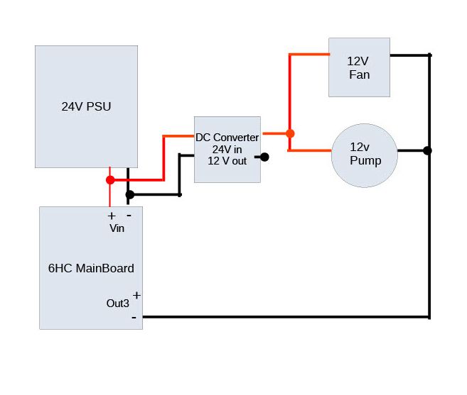
Wiring a 12V water pump
-
Can I do this ?

Essentially I have a 12V water pump (brushless motor) and radiator fan, and a 24V PSU feeding the Duet gen 3 boards. The combined current could exceed the 800mA maximum of the on board 12V regulator. So the plan is to use a 24 to 12 V converter, connect the 12V positive output to the pump and fan and connect the negative side of the pump and fan to negative side of a high current pin such as Out3. The configure Out3 as a fan to be switched thermostatically to the hot end heater. I'm not looking to control the pump speed using PWM - just a simple on/off.
-
Looks good, but if the pump uses a brushed DC motor then I suggest you use OUT1 or OUT2 instead, in case the starting surge of the motor exceeds the ~10A rated current of the fan mosfets.
-
@dc42 said in Wiring a 12V water pump:
Looks good, but if the pump uses a brushed DC motor then I suggest you use OUT1 or OUT2 instead, in case the starting surge of the motor exceeds the ~10A rated current of the fan mosfets.
Thanks, and I could use Out1 or 2 but according to this wiring diagram, https://duet3d.dozuki.com/Wiki/Duet_3_Mainboard_6HC_Wiring_Diagram, it looks like Out 1 to 3 are all high current (with Out 0 being the bed near the top of the board and Out 4 to 9 being low current fan connectors).
-
That's right, OUT 0 can provide the highest current, OUT1 and OUT2 the next highest, and the remaining OUT connectors lower still.
-
@dc42 said in Wiring a 12V water pump:
That's right, OUT 0 can provide the highest current, OUT1 and OUT2 the next highest, and the remaining OUT connectors lower still.
Err, yes but referring back to the schematic and wiring diagram here https://duet3d.dozuki.com/Wiki/Duet_3_Mainboard_6HC_Wiring_Diagram,
Out1, Out2 and Out3 all have the larger JST connectors and all three have V_fused as the input voltage. Whereas Out4 to Out6 have the smaller 4 pin fan connectors and Out7 to 9 have the smaller 2 pin fan connectors and those outputs (4 to 9) all use jumper selectable 24 or 12v voltages.Nothing on that diagram has anything to indicate that Out3 which uses V-fused and has a larger JST connector should only be used for low current devices. So if that is the case, then the diagram ought to be changed because all indications are that it is a higher current capable connector.
-
The schematic at https://github.com/Duet3D/Duet3-Mainboard-6HC/blob/master/Duet3_Mainboard_v1.0/Duet3_MB_schematic_v1.0.pdf shows exactly the same FET on all of OUT1, OUT2 and OUT3 (AOD4184A) and there's no obvious reason why the capacity would be less.
I would assume OUT3 has the same capacity as OUT1 and OUT2.
-
@achrn said in Wiring a 12V water pump:
The schematic at https://github.com/Duet3D/Duet3-Mainboard-6HC/blob/master/Duet3_Mainboard_v1.0/Duet3_MB_schematic_v1.0.pdf shows exactly the same FET on all of OUT1, OUT2 and OUT3 (AOD4184A) and there's no obvious reason why the capacity would be less.
I would assume OUT3 has the same capacity as OUT1 and OUT2.
That was my initial assumption too, and that was how I showed it in my schematic, but @dc42 said I should use OUT1 or OUT2 instead of OUT3.
I can use OUT1 or OUT2 but for future reference, if OUT3 is lower rating than OUT1 or OUT2 then the wiring diagram needs to be amended to reflect that.
-
My mistake, I forgot that we have 3 medium-current outputs on Duet 3 MB6HC, not 2. So I suggest you use any of OUT1, OUT2 and OUT3.
-
@dc42 said in Wiring a 12V water pump:
My mistake, I forgot that we have 3 medium-current outputs on Duet 3 MB6HC, not 2. So I suggest you use any of OUT1, OUT2 and OUT3.
Back to plan A it is then
