• Tags
  • Documentation
  • Order
  • Register
  • Login
Duet3D Logo Duet3D
  • Tags
  • Documentation
  • Order
  • Register
  • Login

IR sensor faulty readings after crash

Scheduled Pinned Locked Moved Solved
IR Height Sensor
3
14
591
Loading More Posts
  • Oldest to Newest
  • Newest to Oldest
  • Most Votes
Reply
  • Reply as topic
Log in to reply
This topic has been deleted. Only users with topic management privileges can see it.
  • undefined
    tetele
    last edited by 14 Jan 2021, 16:56

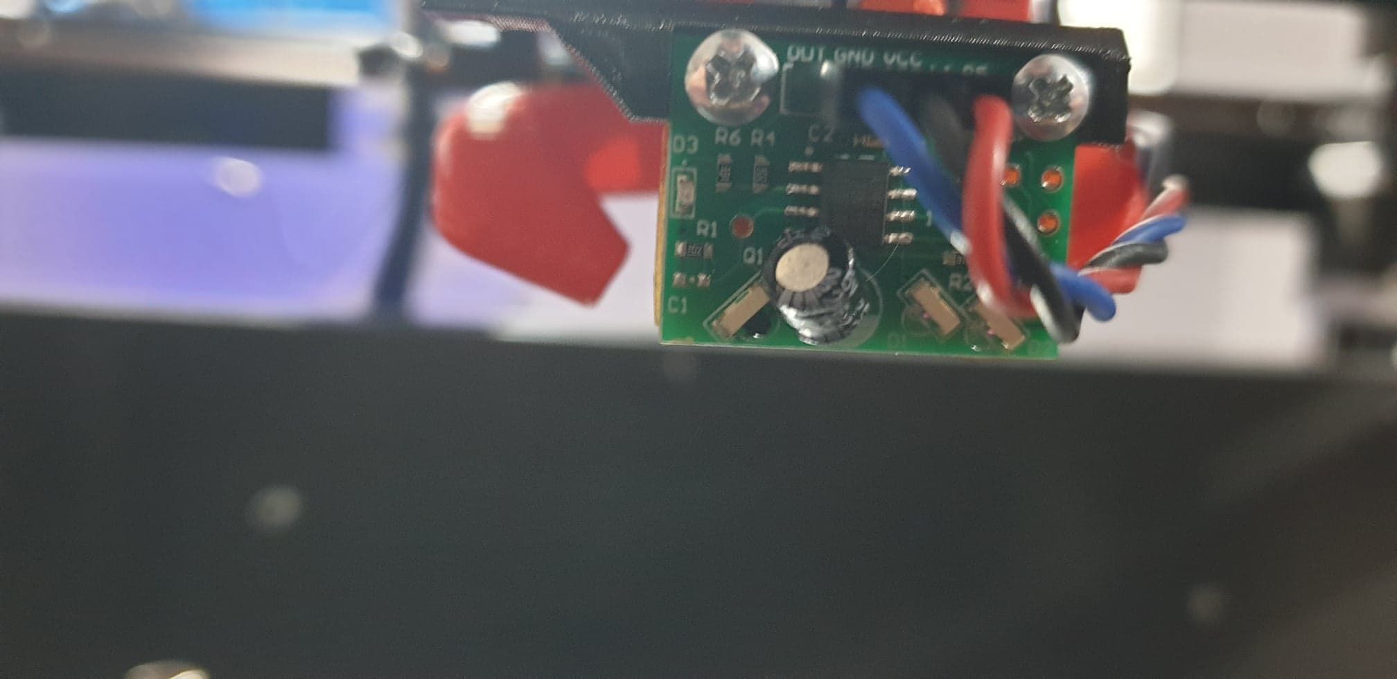
    I've had an IR sensor that came with my BLV MGN Cube kit which worked pretty well until now. A couple of days ago, I crashed it into some calibration print, which almost tore the electrolytic capacitor (connections were bent pretty badly). Luckily, it was mounted on a sort of an arm which had enough flexibility to prevent the PCB from breaking.

    IR.jpg

    Ever since then, the sensor triggers twice: once at about 10-15mm, then again at about 2-3mm. I thought the capacitor was the problem, so I re-soldered a replacement (same specs - 22uF 25V). No changes to the behavior.

    https://imgur.com/a/JHD82j3

    I have read that the double triggering was an issue with older versions of the firmware (I don't know what firmware version mine has), but I can't imagine how that would change only after a crash.

    Any suggestions apart from getting a new one?

    1 Reply Last reply Reply Quote 0
    • undefined
      dc42 administrators
      last edited by dc42 15 Jan 2021, 07:33

      Make sure that the electrolytic capacitor is the same size as the original and mounted flush to the board. Its primary purpose is to block light passing directly from the IR emitters to the IR sensor. The value doesn't matter but the size does.

      C1 is not supposed to be fitted.

      Duet WiFi hardware designer and firmware engineer
      Please do not ask me for Duet support via PM or email, use the forum
      http://www.escher3d.com, https://miscsolutions.wordpress.com

      undefined 1 Reply Last reply 15 Jan 2021, 08:01 Reply Quote 0
      • undefined
        Phaedrux Moderator
        last edited by 14 Jan 2021, 20:04

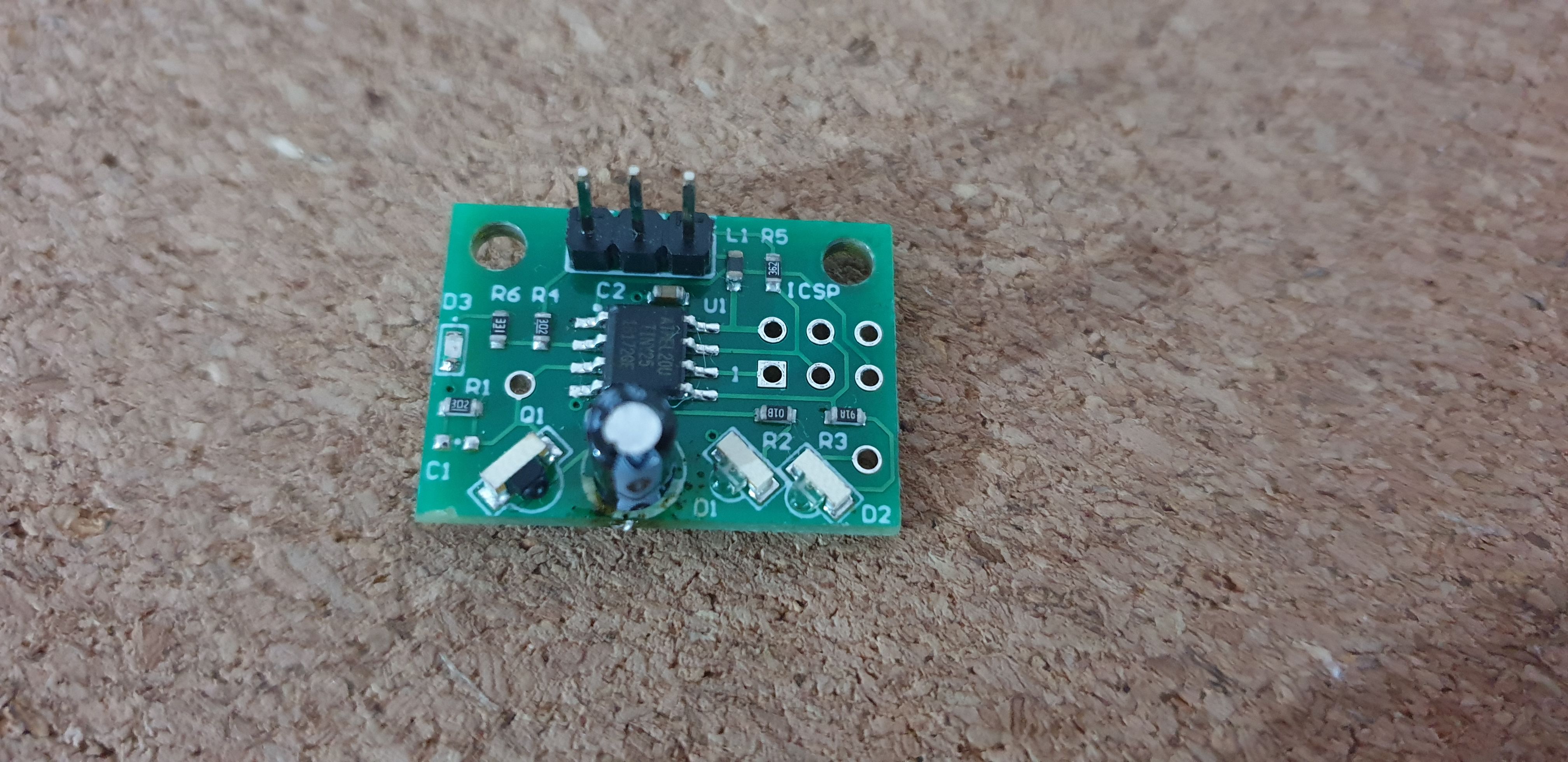
        Can you unmount the sensor and get some good photos? Maybe something else has been dislodged.

        Z-Bot CoreXY Build | Thingiverse Profile

        1 Reply Last reply Reply Quote 0
        • undefined
          tetele
          last edited by 14 Jan 2021, 20:37

          Let me know if you need any specific angle. And thanks!

          2021-01-14 22.35.23.jpg 2021-01-14 22.35.17.jpg

          1 Reply Last reply Reply Quote 0
          • undefined
            Phaedrux Moderator
            last edited by Phaedrux 14 Jan 2021, 21:51

            Is there some thing missing at C1 in lower left?

            Is this a DC42 IR sensor or a clone?

            Z-Bot CoreXY Build | Thingiverse Profile

            1 Reply Last reply Reply Quote 0
            • undefined
              tetele
              last edited by 14 Jan 2021, 21:57

              C1 is empty, there are only blank solder pads there. I don't exactly know if it's a clone or not, I got it in a BLV MGN Cube kit, like I said.

              1 Reply Last reply Reply Quote 0
              • undefined
                Phaedrux Moderator
                last edited by 14 Jan 2021, 22:01

                e3b80f0a-7f18-4d1d-9167-b04fb4b31b9b-image.png

                C1 is populated in this image of the Duet IR sensor.

                Z-Bot CoreXY Build | Thingiverse Profile

                1 Reply Last reply Reply Quote 0
                • undefined
                  Phaedrux Moderator
                  last edited by 14 Jan 2021, 22:03

                  Maybe the emitter or sensor got nudged a bit too, so it's detecting the surface from two different heights because the emitters don't converge anymore. Just a guess.

                  https://miscsolutions.wordpress.com/mini-height-sensor-board/

                  See the modifications section.

                  Z-Bot CoreXY Build | Thingiverse Profile

                  1 Reply Last reply Reply Quote 0
                  • undefined
                    tetele
                    last edited by tetele 14 Jan 2021, 22:15

                    It's super plausible that my board is a clone, but that does not explain why it used to work and now it doesn't. There was never a capacitor or any other SMD part at C1.

                    I think that the only thing that got knocked in the crash was the large electrolytic capacitor, but there is a chance it might have moved the sensor a bit, as it was bent towards the left.

                    Be that as it may, my optical components are SMD so the barbaric plier technique does not apply 😁

                    But thanks a lot for trying to help!

                    1 Reply Last reply Reply Quote 0
                    • undefined
                      dc42 administrators
                      last edited by dc42 15 Jan 2021, 07:33

                      Make sure that the electrolytic capacitor is the same size as the original and mounted flush to the board. Its primary purpose is to block light passing directly from the IR emitters to the IR sensor. The value doesn't matter but the size does.

                      C1 is not supposed to be fitted.

                      Duet WiFi hardware designer and firmware engineer
                      Please do not ask me for Duet support via PM or email, use the forum
                      http://www.escher3d.com, https://miscsolutions.wordpress.com

                      undefined 1 Reply Last reply 15 Jan 2021, 08:01 Reply Quote 0
                      • undefined
                        tetele @dc42
                        last edited by 15 Jan 2021, 08:01

                        @dc42 thank you! That makes a lot of sense, as the old capacitor was pried from the board, leaving light through.

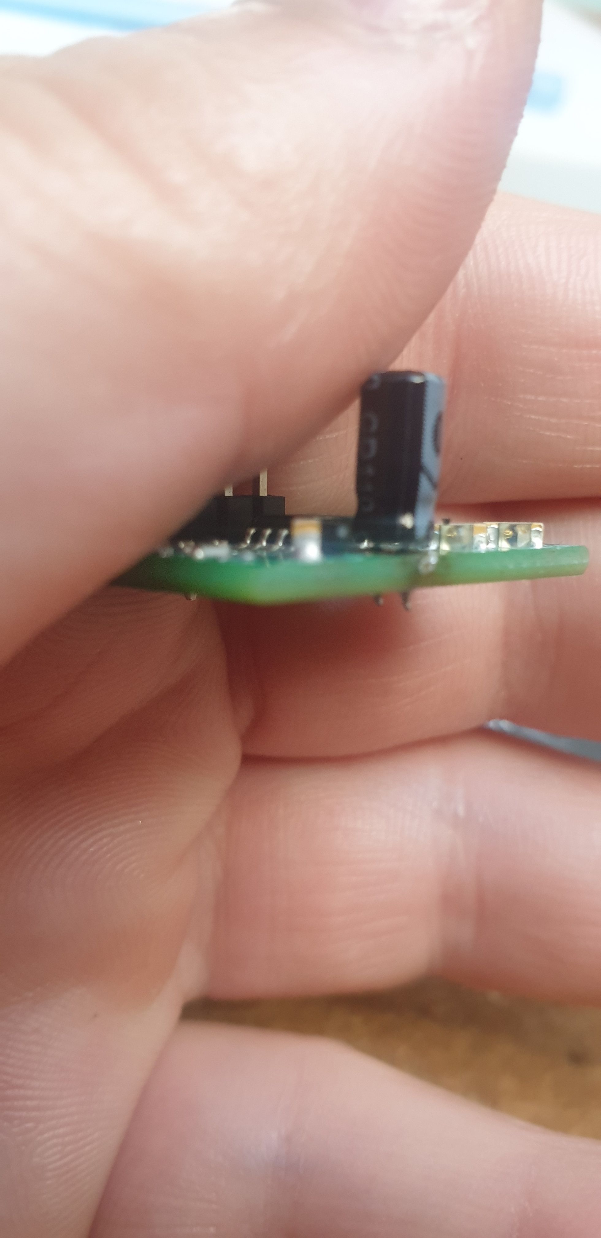
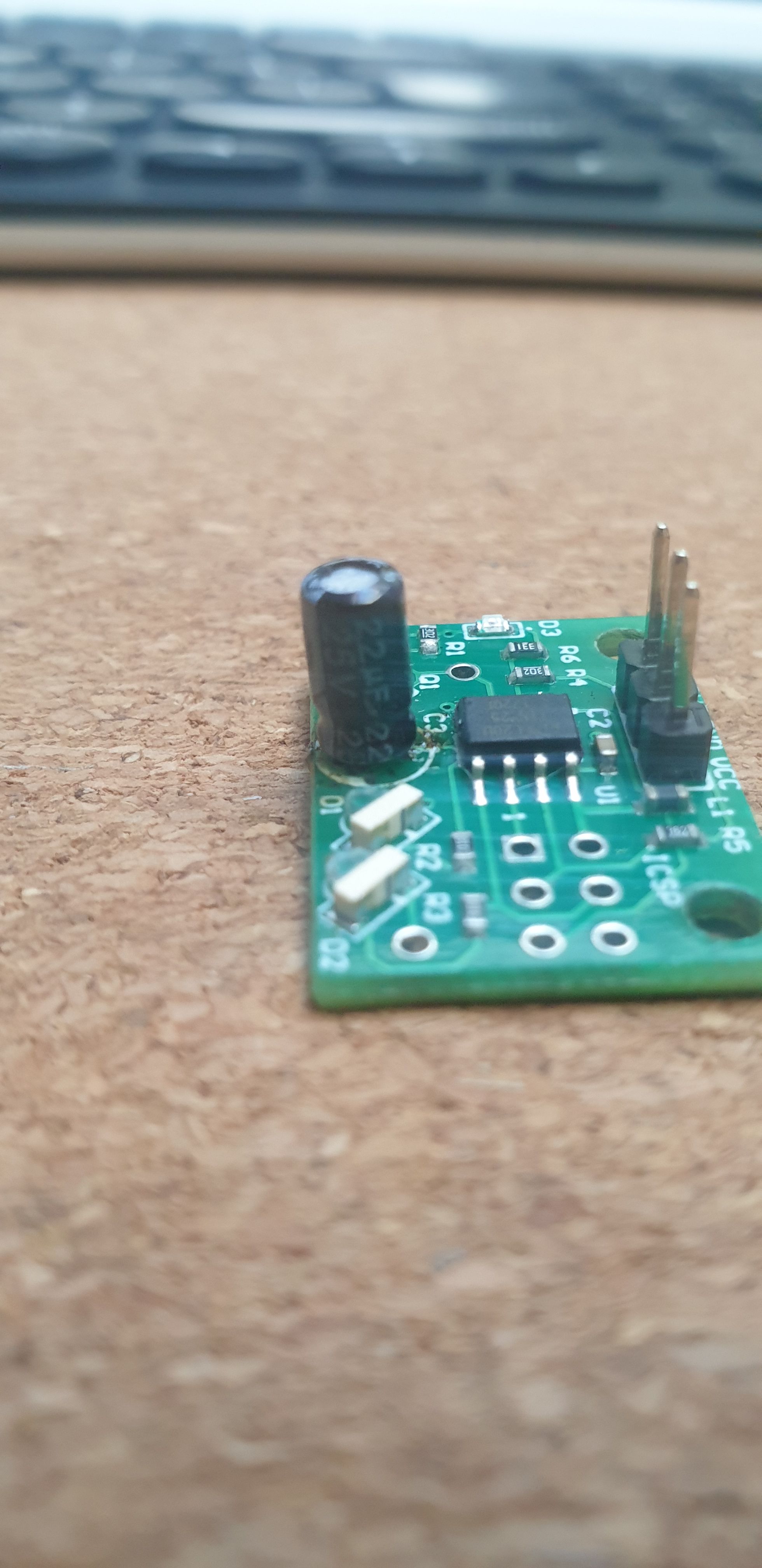
                        At the moment, the one I re-soldered is neither the same size as the original, nor flush with the board. I didn't realize that it's used to block light.

                        Can you tell me if I can use a different voltage or capacity? I do have other capacitors that are thicker, but only in different specs.

                        1 Reply Last reply Reply Quote 0
                        • undefined
                          dc42 administrators
                          last edited by 15 Jan 2021, 08:32

                          Yes, as long as the voltage rating is at least 6.3V (preferably at least 10V) you can use a different value. We have used both 10uF and 22uF in production.

                          Duet WiFi hardware designer and firmware engineer
                          Please do not ask me for Duet support via PM or email, use the forum
                          http://www.escher3d.com, https://miscsolutions.wordpress.com

                          undefined 1 Reply Last reply 15 Jan 2021, 08:51 Reply Quote 0
                          • undefined
                            tetele @dc42
                            last edited by 15 Jan 2021, 08:51

                            @dc42 Thanks a lot! I don't have any larger replacement on hand, I need to order some. Would creating a shroud or any opaque barrier between the emitters and receiver help? I could simply try to stick the capacitor closer to the board, you can hopefully see it's not that far away or that small.

                            2021-01-15 10.50.47.jpg 2021-01-15 10.48.41.jpg

                            1 Reply Last reply Reply Quote 0
                            • undefined
                              dc42 administrators
                              last edited by 15 Jan 2021, 09:18

                              Yes an opaque barrier should work.

                              The capacitors we use in that position include Farnell part# 9452389 and RS part# 706-0488. They are 5mm high x 5mm diameter with 2mm lead spacing.

                              Duet WiFi hardware designer and firmware engineer
                              Please do not ask me for Duet support via PM or email, use the forum
                              http://www.escher3d.com, https://miscsolutions.wordpress.com

                              1 Reply Last reply Reply Quote 0
                              • undefined
                                tetele
                                last edited by 15 Jan 2021, 09:27

                                Holy crap, it seems to have worked! I soldered the capacitor flush with the board and it seems to be triggering only in the 2-4mm range. I used my 4x7mm capacitor that I had on hand, but the main thing was to make sure light does not bleed under it.

                                Probably that's what happened when the old one got knocked, a slit was formed under it that allowed the light to pass, even if the electrical connections were not broken.

                                Thanks a lot @dc42!

                                1 Reply Last reply Reply Quote 1
                                1 out of 14
                                • First post
                                  1/14
                                  Last post
                                Unless otherwise noted, all forum content is licensed under CC-BY-SA