• Tags
  • Documentation
  • Order
  • Register
  • Login
Duet3D Logo Duet3D
  • Tags
  • Documentation
  • Order
  • Register
  • Login

Use 5v from diffrent source for optical endstops? on duetwifi

Scheduled Pinned Locked Moved
Duet Hardware and wiring
8
28
3.2k
Loading More Posts
  • Oldest to Newest
  • Newest to Oldest
  • Most Votes
Reply
  • Reply as topic
Log in to reply
This topic has been deleted. Only users with topic management privileges can see it.
  • undefined
    StAnZ-007
    last edited by 3 Jan 2020, 20:59

    @bearer said in Use 5v from diffrent source for optical endstops? on duetwifi:

    you'd need to ensure the output- is connected to ground on the duet. usually input- and output- are the same, so if you feed it Vin from the duet that should be okay. then verify the duet inputs are okay with the signal level, no idea of they active high or low, or if the duet can take 5v on all inputs.

    The sensor are active high.
    If I found good information here, duet board v1.04 can accept +5v on sensor inputs

    1 Reply Last reply Reply Quote 0
    • ?
      A Former User
      last edited by 3 Jan 2020, 21:00

      then make sure you have a common ground and you'll be golden with your plan

      1 Reply Last reply Reply Quote 0
      • undefined
        dc42 administrators @StAnZ-007
        last edited by dc42 1 Mar 2020, 21:15 3 Jan 2020, 21:14

        @StAnZ-007 said in Use 5v from diffrent source for optical endstops? on duetwifi:

        Hello,

        I know it's a old post, but I didn't want to create a new one just for 1 question.

        I have adapted a Duet2Wifi v1.04 on ATOM 2.5EX Delta printer, and I have a question about optical limit sensor.
        The sensors are OMRON trade parts and were connected on +5v on the old board.
        The sensor didn't work with +3.3v on the duet, then I need to go to +5v external power

        My question is simple, can I just connect the signal pin on the Duet and no connection for the +3.3v and ground pin or need I connect signal pin + ground pin on the duet board.
        I would like to connect +5v and ground on the adapter below and just the sensor signal pin to the duet board.
        Is it possible ?

        alt text

        Thanks for your support.

        Thar adaptor is overkill. You can get +5V from either the PanelDue connector or from the expansion connector. And yes, the Duet WiFi/Ethernet rev 1.04 tolerates 5V on the endstop inputs.

        Duet WiFi hardware designer and firmware engineer
        Please do not ask me for Duet support via PM or email, use the forum
        http://www.escher3d.com, https://miscsolutions.wordpress.com

        1 Reply Last reply Reply Quote 0
        • undefined
          StAnZ-007
          last edited by 3 Jan 2020, 21:16

          @dc42 said in Use 5v from diffrent source for optical endstops? on duetwifi:

          e connector or from the expansion connector.

          OK, if I use the +5v from pin 1, can I give the power to 5 sensors at the same time on the Pin 1 alone ?

          undefined 1 Reply Last reply 3 Jan 2020, 21:40 Reply Quote 0
          • undefined
            dc42 administrators @StAnZ-007
            last edited by 3 Jan 2020, 21:40

            @StAnZ-007 said in Use 5v from diffrent source for optical endstops? on duetwifi:

            @dc42 said in Use 5v from diffrent source for optical endstops? on duetwifi:

            e connector or from the expansion connector.

            OK, if I use the +5v from pin 1, can I give the power to 5 sensors at the same time on the Pin 1 alone ?

            Yes.

            Duet WiFi hardware designer and firmware engineer
            Please do not ask me for Duet support via PM or email, use the forum
            http://www.escher3d.com, https://miscsolutions.wordpress.com

            1 Reply Last reply Reply Quote 0
            • undefined
              StAnZ-007
              last edited by 3 Jan 2020, 21:44

              @dc42 said in Use 5v from diffrent source for optical endstops? on duetwifi:

              Yes.

              Thanks for your fast answer.

              1 Reply Last reply Reply Quote 0
              • undefined
                StAnZ-007
                last edited by 3 Jan 2020, 21:51

                So last question,

                • Can I connect all my 5v sensor pin to the expansion pin 1 ? => OK, it's clear for me
                • Then can I connect all my ground sensor pin to the expansion pin 2 ?
                • Then can I connect only signal to X Stop / Y stop / Z stop / E1 ans E2 stop ?

                Possible or not ?

                Thanks

                1 Reply Last reply Reply Quote 0
                • undefined
                  dc42 administrators
                  last edited by 3 Jan 2020, 21:53

                  Yes, that's workable.

                  Duet WiFi hardware designer and firmware engineer
                  Please do not ask me for Duet support via PM or email, use the forum
                  http://www.escher3d.com, https://miscsolutions.wordpress.com

                  1 Reply Last reply Reply Quote 0
                  • undefined
                    StAnZ-007
                    last edited by 3 Jan 2020, 21:56

                    Nice, thanks

                    1 Reply Last reply Reply Quote 0
                    • undefined
                      KroVex
                      last edited by 4 Jan 2020, 15:11

                      Hi all,

                      I also have problems with the optical endstops. The board I have is the Duet2Wifi v1.04 and the endstops are TCST2103 5v optical sensors (https://www.vishay.com/docs/81147/tcst2103.pdf).

                      VCC is connected to 5v Powersupply
                      GND to GND on the endstop-pin on the Board
                      SIG to STP/IN on the endstop-pin on the Board

                      The endstops are in the config.g File set to Active-High (M574 X2 Y2 Z2 S1).

                      If the sensors are triggered, the endstop LEDs on the board go out. But nothing happens in web control -> it shows all sensors are triggered.
                      No i have measured the sensor signals:
                      If the sensor is triggered, the output is 4.3v
                      If the sensor is not triggered, the output is 1.5v, and not 0v or GND...

                      Have I missed something or are my sensors just crap?

                      Thanks for Help.

                      undefined 1 Reply Last reply 4 Jan 2020, 19:00 Reply Quote 0
                      • undefined
                        dc42 administrators @KroVex
                        last edited by 4 Jan 2020, 19:00

                        @KroVex said in Use 5v from diffrent source for optical endstops? on duetwifi:

                        Hi all,

                        I also have problems with the optical endstops. The board I have is the Duet2Wifi v1.04 and the endstops are TCST2103 5v optical sensors (https://www.vishay.com/docs/81147/tcst2103.pdf).

                        VCC is connected to 5v Powersupply
                        GND to GND on the endstop-pin on the Board
                        SIG to STP/IN on the endstop-pin on the Board

                        The endstops are in the config.g File set to Active-High (M574 X2 Y2 Z2 S1).

                        If the sensors are triggered, the endstop LEDs on the board go out. But nothing happens in web control -> it shows all sensors are triggered.
                        No i have measured the sensor signals:
                        If the sensor is triggered, the output is 4.3v
                        If the sensor is not triggered, the output is 1.5v, and not 0v or GND...

                        Have I missed something or are my sensors just crap?

                        Thanks for Help.

                        The datasheet you linked to is for a bare slotted opto sensor, and as such it does not require 5V. But it does need sufficient forward current in the IR diode to turn the phototransistor fully on. Please provide the schematic of the complete endstop device that uses that sensor, including the values of the resistors on it (there are probably 2 of them).

                        Duet WiFi hardware designer and firmware engineer
                        Please do not ask me for Duet support via PM or email, use the forum
                        http://www.escher3d.com, https://miscsolutions.wordpress.com

                        1 Reply Last reply Reply Quote 0
                        • undefined
                          KroVex
                          last edited by 4 Jan 2020, 19:42

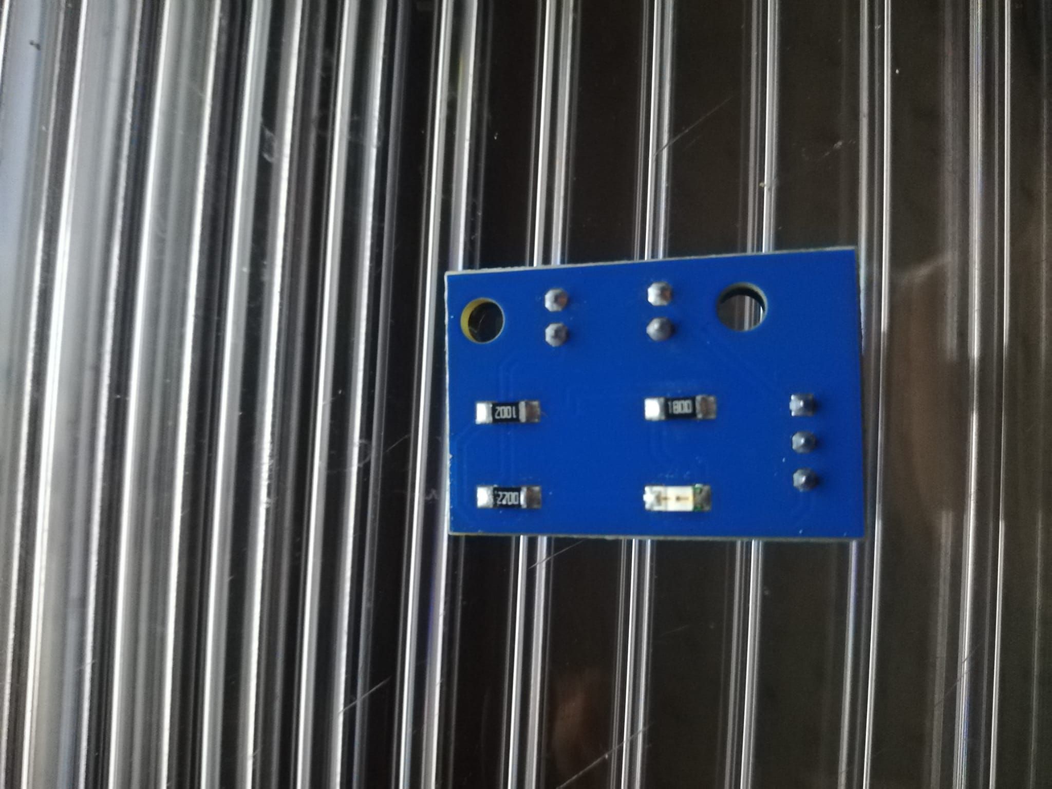
                          I could not find the original data sheet because the manufacturer (germanreprap.com) has closed its forum.
                          But maybe the pictures will help:
                          77d5d998-de82-47d6-92e7-a77858c2b438.jpg 2c44500b-51e9-43f3-9abb-370abb0747c1.jpg

                          Three resistors are installed on the back of the sensors: 1002, 1800, 2200

                          1 Reply Last reply Reply Quote 0
                          • undefined
                            KroVex
                            last edited by 4 Jan 2020, 20:59

                            Problem solved!

                            A good tip was that the sensor does not need 5v.
                            However, the homex / y / z.g files from e.g. G1 H2 Z5 F6000 must be changed to G1 S2 Z5 F6000 (H to S). Now the motors stop when the sensor is triggered.

                            Thx for Help.

                            undefined 1 Reply Last reply 4 Jan 2020, 22:17 Reply Quote 0
                            • undefined
                              dc42 administrators @KroVex
                              last edited by dc42 1 Apr 2020, 22:18 4 Jan 2020, 22:17

                              @KroVex said in Use 5v from diffrent source for optical endstops? on duetwifi:

                              However, the homex / y / z.g files from e.g. G1 H2 Z5 F6000 must be changed to G1 S2 Z5 F6000 (H to S). Now the motors stop when the sensor is triggered.

                              Then you must be using quite old firmware.

                              Duet WiFi hardware designer and firmware engineer
                              Please do not ask me for Duet support via PM or email, use the forum
                              http://www.escher3d.com, https://miscsolutions.wordpress.com

                              1 Reply Last reply Reply Quote 0
                              • undefined
                                Googliola
                                last edited by 6 Mar 2020, 09:49

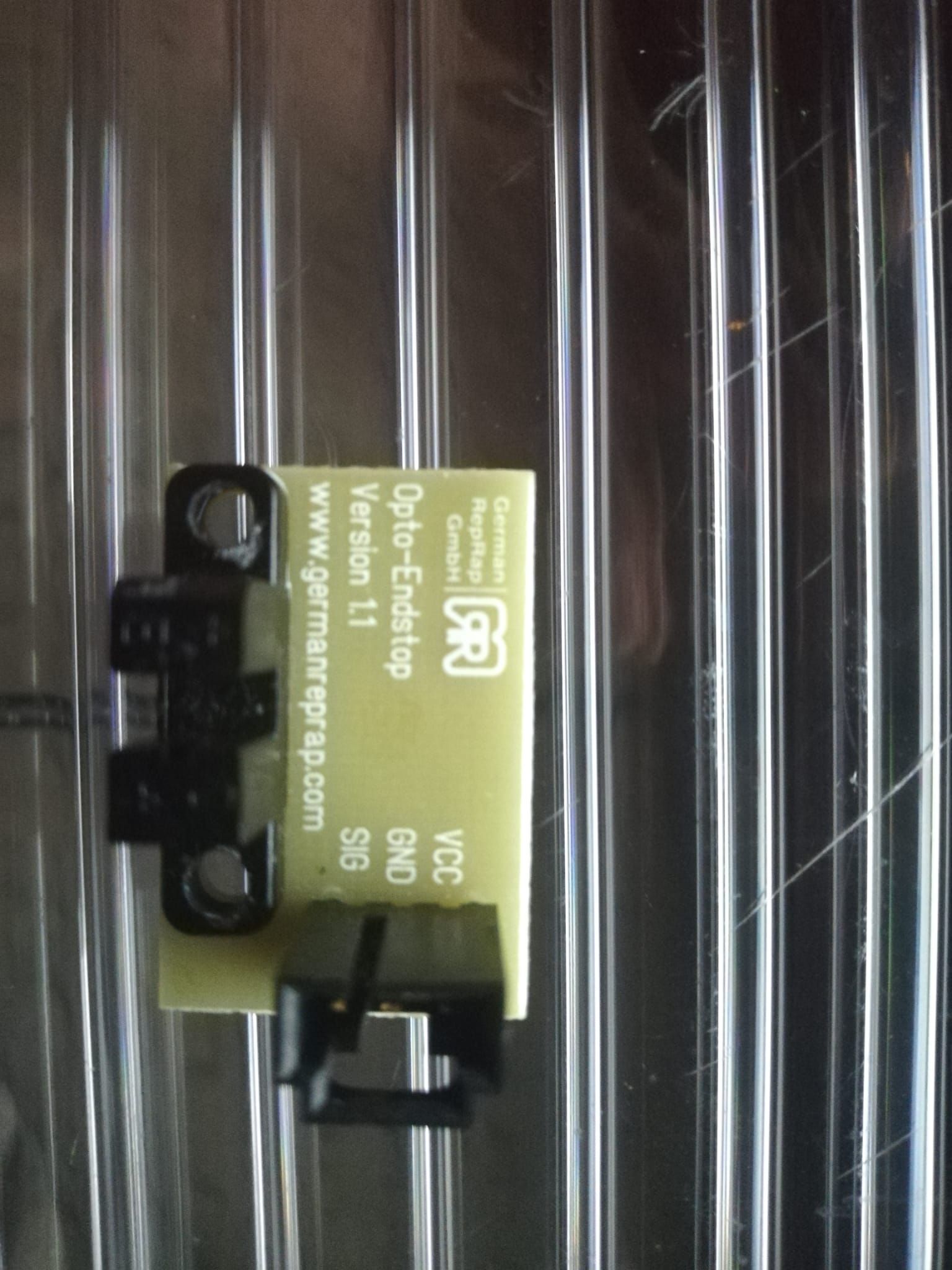
                                The board I have is the Duet2Wifi v1.02 and the endstops are most likely 5v (see pic), so no luck with that combo. I read somewhere in this forum that it is possible to convert them to 3.3v by adding a resistor. My know-how for these things is close to zero, so could anyone point me to right resistor and what Ohm I need to add (on top of SMD resistor)?
                                IMG_20200306_103533[1].jpg

                                1 Reply Last reply Reply Quote 0
                                • undefined
                                  dc42 administrators
                                  last edited by dc42 3 Jun 2020, 20:03 6 Mar 2020, 12:02

                                  That endstop may work on 3.3V already. If it doesn't, then I suspect that R1 is the critical component. The picture is a little out of focus, so I can't read the label on it - what is it? Can you measure its value with a multimeter?

                                  Duet WiFi hardware designer and firmware engineer
                                  Please do not ask me for Duet support via PM or email, use the forum
                                  http://www.escher3d.com, https://miscsolutions.wordpress.com

                                  undefined 1 Reply Last reply 7 Mar 2020, 09:41 Reply Quote 0
                                  • mrehorstdmdundefined
                                    mrehorstdmd
                                    last edited by 6 Mar 2020, 14:00

                                    FWIW, these endstops work fine on 3.3V:

                                    https://www.amazon.com/gp/product/B07JMDLD84/ref=ppx_yo_dt_b_asin_title_o05_s00?ie=UTF8&psc=1

                                    I have two now, and soon three of them, in UMMD.

                                    https://drmrehorst.blogspot.com/

                                    1 Reply Last reply Reply Quote 0
                                    • undefined
                                      Googliola @dc42
                                      last edited by 7 Mar 2020, 09:41

                                      @dc42 said in Use 5v from diffrent source for optical endstops? on duetwifi:

                                      l component. The picture is a little out of focus, so I can't read the label on it - what is it? Can you measure its value with a multimeter?

                                      Hmmm, when I connected them 18 months ago, they did not work...now they do?! Probably my fault. So just for future reference: Optical endstops V1.1 from Trianglelabs are 3.3V tolerant. Yeeeha.
                                      @dc42 thanks for your support (R1 is 470, R6 is 750, all the other 10k Ohm)
                                      @mrehorstdmd thanks for your input as well. On a sidenote: your (coreXY) blog posts are tremendously helpful. So thanks for that too!

                                      1 Reply Last reply Reply Quote 0
                                      • First post
                                        Last post
                                      Unless otherwise noted, all forum content is licensed under CC-BY-SA