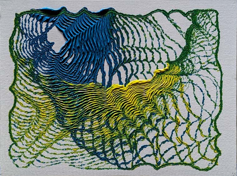
15 hours at 40 mm/sec, 1mm nozzle, 1.2 mm line width, 0.3 mm layers, vase mode in Cura, 923g of PETG filament, 638 mm tall:
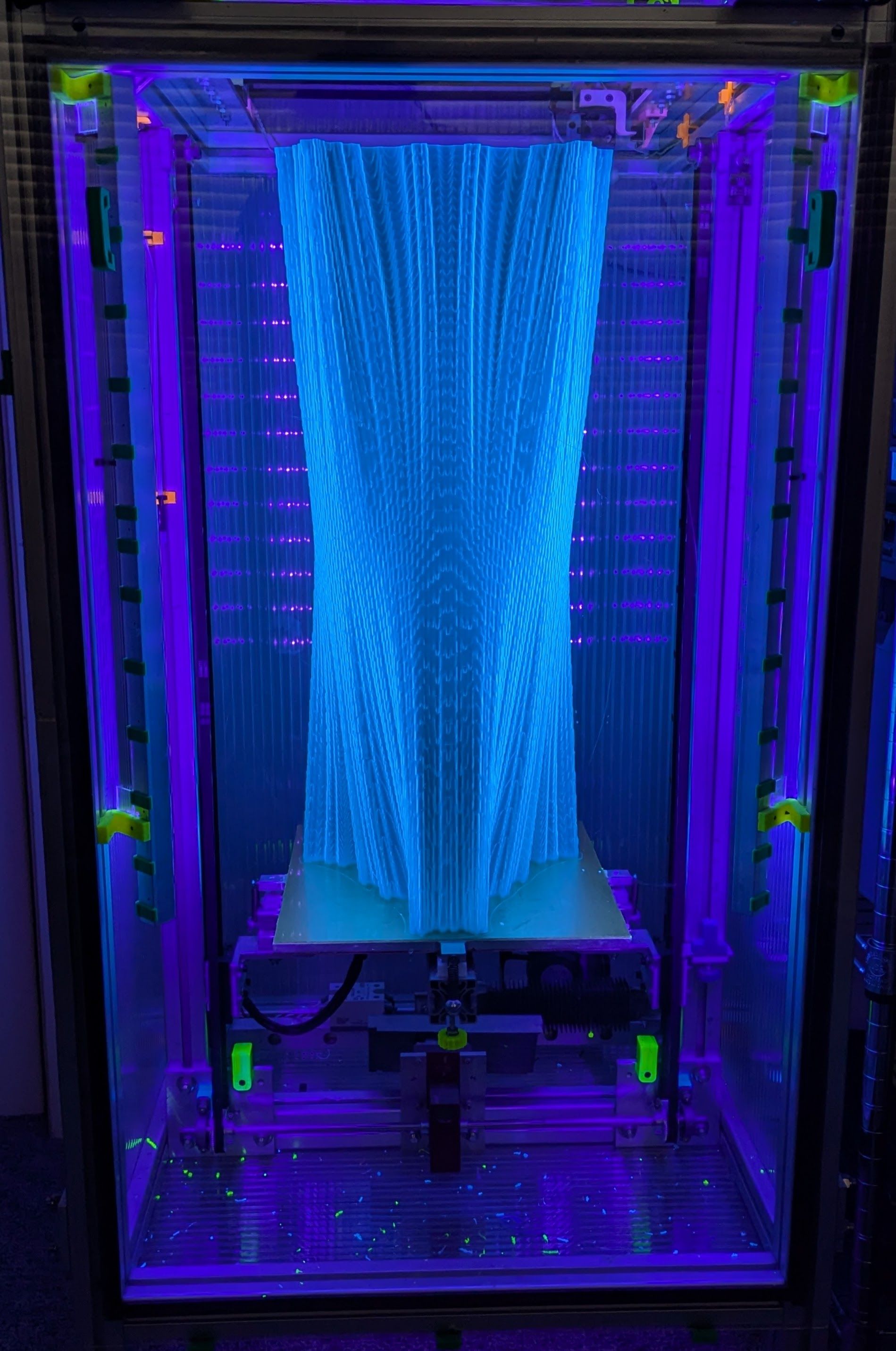
It's going to become a lamp.
I'm a dentist who likes to build 3D printers. I spend a lot of time at the Milwaukee Makerspace.
15 hours at 40 mm/sec, 1mm nozzle, 1.2 mm line width, 0.3 mm layers, vase mode in Cura, 923g of PETG filament, 638 mm tall:
It's going to become a lamp.
Here is Ms. Kitty enjoying my corexy sand table running a circular erase pattern at 1500 mm/sec with acceleration of 10k mm/sec^2.
The table is driven by two servomotors with a Duet2 WiFi controller.
You're essentially asking about the difference between a Kelvin and a Maxwell kinematic coupling.
The "rails" have to run parallel to the direction that the plate expands, relative to the chosen reference point. The reference point location relative to the adjustments is what makes it a Kelvin or Maxwell coupling.
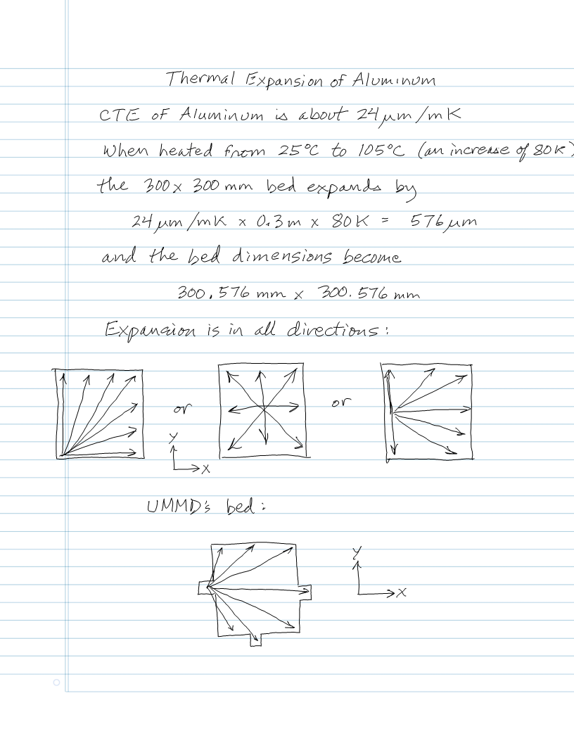
If you choose the reference point to be the center of the bed, the "rails" should be aligned to point at the center of the bed at all three support points because the bed expands outward in all directions from there. That's the classic Maxwell coupling.
OTOH, if you choose one of the screws to be the reference point, say one of the two along the bottom edge, that point won't need rails- just a "hole" to sit in. The rails at the other point along the bottom edge will simply be parallel to the bottom edge (in your drawing) of the plate, and the third will just support the flat bottom of the plate and is allowed to slide in X and Y. You'll adjust the bottom edge point first to set the edge of the plate parallel to printer's X axis, and then set roll using the third point to set the plate parallel to printer's Y axis. This is a Kelvin mount.
The Kelvin mount's square angles are easier to set up accurately - most machine tools are square- than the odd angles that will result if you choose the reference to be any other point (as in a Maxwell mount), and you only need "rails" at one point, not all three.
If the rails are set square to each other (Kelvin style) and the lines they define are parallel to the X and Y axes of the printer, leveling the bed is super easy because a) you'll only need to adjust two leveling points and b) when you make the adjustments all tilting will be in the directions of the X and Y axes of the printer.
I used a Kelvin mount in my printer, with the reference being a point on one of the "ears" on the plate:
In the Maxwell mount, every leveling adjustment, tilts the bed in X and Y, so tramming isn't quite as simple. Also, every tramming adjustment moves the reference point vertically, so you have to adjust the Z=0 position once the bed is level. It's only a Maxwell mount if you accurately aim the rails at the reference point. Any error will cause the bed to tilt and move up and down a bit as it heats up.
With the Kelvin mount, the reference point doesn't move vertically when you tram the bed, and each adjustment (provided you adjust pitch first, then roll) only tilts the bed along one axis. That means that when you adjust roll, it doesn't affect the pitch adjustment.
Of course, if you use auto tramming and zeroing, difficulties in adjustment shouldn't matter...
My coffee table, aka Arrakis 2.0, is a servomotor powered coreXY mechanism that is normally used to magnetically drag a steel ball to create pretty patterns in sand. My cat enjoys chasing the ball, especially when the table is running a spiral erase pattern at 1000 mm/sec.
I decided to try to create patterns that she might like, so I wrote a spreadsheet that generates random motion of the type that attracts her attention. I enter the table dimensions, the desired speed range, and desired dwell time range and the spreadsheet creates gcode that causes the ball to move in random directions at random speeds and then stops for a random amount of time, before darting away, sort of like a small animal might behave. Ms. Kitty loves it!
The spreadsheet generates 500 lines of gcode that typically take about 16 minutes to run on the table, about 3x longer than Ms. Kitty's attention span.
More: blog post
I recently installed opto endstops in my corexy printer and ran some tests of their precision.
In the X and Y axes I ran two identical prints with the first homing normally at the start of the print and the second rehoming X and Y after each layer change. The result is that the prints are barely distinguishable under high magnification and are essentially identical without magnification, indicating that the precision of the optical endstops is very high. Here are two photos of the prints that contain the largest visible difference between them:
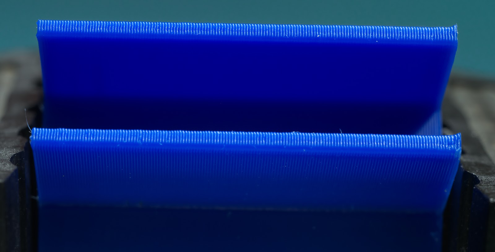
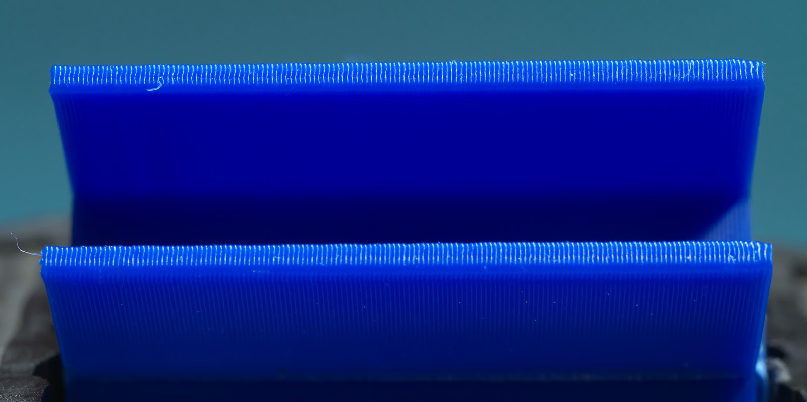
Why would anyone want to home a print at every layer change? MarkForged printers use that feature to automatically detect and stop layer-shifted prints. If you are printing expensive material such as PEEK, PEKK, Ultem, etc., you want the print to stop pretty quickly if there's a problem like layer shifting. I'm thinking about how to program a macro that will detect layer shifting in printers running Duet controllers.
I also tested the Z axis opto endstop. I mounted a digital gauge on the printer's frame with the probe contacting the bed, then homed the machine and zeroed the gauge. I moved the bed down random amounts and rehomed 10 times to see if the bed would return to the same position as indicated by the gauge. 8 out of 10 times it went to 0.00 mm and the other 2 times it went to 0.01 mm. The Z axis in my printer is configured for 16:1 ustepping, interpolation on, and 800 steps/mm.
Video here: Z axis homing precision test
The typical way to adjust the Z=0 position is to use a screw to bump a microswitch. The problem with that is when you're zeroing the Z axis you need to be able to make very small adjustments to the home position of the bed/extruder. If you use an M4x0.7 screw, one turn of the screw moves the home position by 700 um- that's more than 3 full 200 um print layers. If you need to move the home position 30 um, that's 1/23 of a turn - not too easy to do without overshooting.
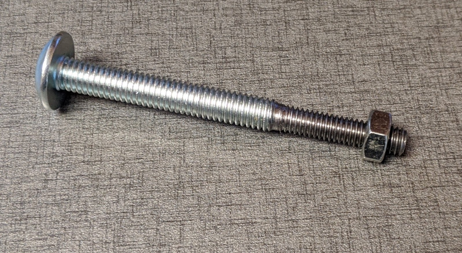
I designed a differential screw adjuster to go with the optical endstop in the Z axis. It uses a M5x0.8 screw with the end 20 mm or so turned down to 4 mm and rethreaded with a M4x0.7 mm die. The result is an adjuster that moves the home position of the bed by 100 um for each full turn of the adjuster, making it very easy to make small adjustments.

While I was running the other tests I checked the adjuster, too. The result- about 100 um per turn of the adjuster, as expected.
Video: Differential screw Z=0 adjuster test
One of the best things about opto endstops is the cost. 3 for $10. They work fine with the 3.3V that the Duet supplies. They also don't seem to mind the 50C temperature inside my printer's enclosure when I'm printing ABS. These endstops have LEDs that light up when they are triggered, making the Z=0 position adjustment easy because you don't have to check the control panel of the printer - just turn the adjuster until the light comes on.
More here:
https://drmrehorst.blogspot.com/2020/03/a-new-z-axis-optical-endstop-design-for.html
https://drmrehorst.blogspot.com/2020/03/testing-ummds-xy-optical-endstops.html
https://drmrehorst.blogspot.com/2020/03/testing-ummds-new-z-axis-optical.html
I occasionally see people posting about using servomotors here. One thing you should know about them is that they can wipe out your controller board, power supply, and any other connected electronics if you are not very careful in their use. I was uncareful and learned this the hard way when I was building the Arrakis sand table.
I had slightly reduced the size of the corexy mechanism, but failed to update the travel limits in the config.g file. I then ran an old pattern file that was generated at the original, larger size on the new, smaller mechanism. I think all this happened before I had my morning coffee. The machine homed itself then took off at 1500 mm/sec and promptly slammed into the physical end of the Y axis, bringing the servomotors to an abrupt halt. That caused a voltage surge on the power supply line that destroyed the Duet2 WiFi controller board, the power supply, and some buck converters that were used to power LED strips.
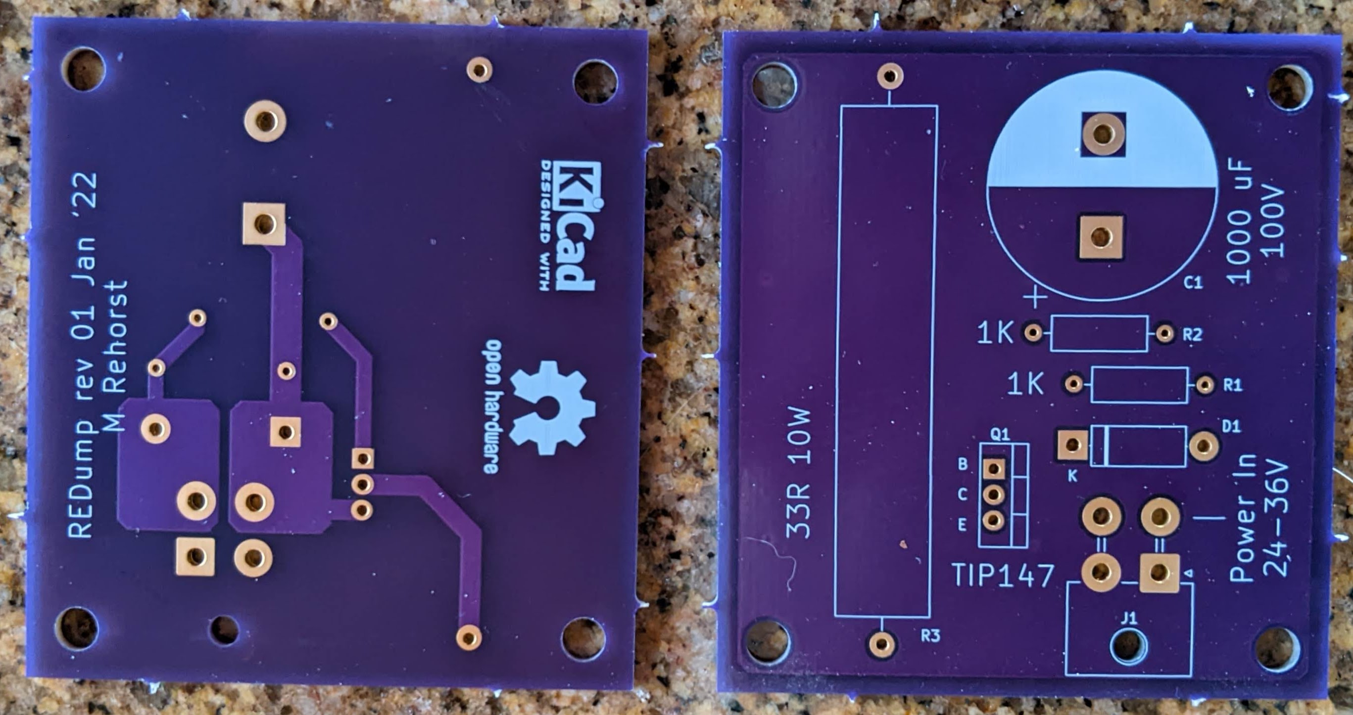
Someone pointed me at an app note on the Gecko Drives web site that will protect from exactly this sort of problem (and mechanical failures like seized bearings, or someone/something (cats?) blocking the mechanism. This is the circuit:
I designed a PCB, ordered parts, and after waiting months for backordered connectors, decided not to wait any more. I built a couple boards and ran a test of the circuit prior to installing the servomotors in my 3D printer. The protection circuit appears to work as expected. The abruptly stopped motor generates a voltage spike that gets dissipated in the 33 Ohm 10W resistor and the spike is never seen by the power supply.

@MartinNYHC said in Belt tension:
Just finished my BLV mgn cube build and now need to fine tune all the stuff. I'm wondering what the right belt tension is. Are there any rules of thumb?
There are just two rules of thumb for corexy machine belt tension:
If the belts are too tight, you'll be putting a lot of force on the pulley and motor mounts, and if they are stacked belt type that stand up like a fence post, they are liable to flex inward. The mechanism may not move smoothly and may bind depending on the type of linear bearings and the design of the pulley mounts. If you see pulleys tilting inward, you're putting too much tension on the belts (or you need to redesign motor or pulley mounts).
If the belts are too loose they may slip on the drive pulleys - that's MUCH too loose. If they are so tight that the mechanism won't move smoothly, they are too tight. You want them to be somewhere between those extremes, and just about anywhere between those extremes will work fine.
Before you tension the belts, the X and Y axes should be square. When you tension the first belt, they X and Y axes will usually be pulled out of square an amount that will vary depending on the flexibility of the X axis assembly, the type of bearings and guide rails used, and the absolute tension applied.
When you tension the second belt, it will also increase tension on the first belt that you already tensioned, so when you tension the first belt, leave it a little looser than you feel is sufficient. Then, when you tension the second belt, the first one will tighten up. You are done adjusting tension when the X and Y axes are square and the belts are tight but not too tight. Usually, the belts will be close to equal tension when you're done, but getting the axes square is the final indicator, not equal belt tension.
If the belt tension varies as you move the extruder carriage around, the pulleys guiding the belts are not positioned correctly, and a major redesign is in order.
I put an LED and coin cell battery in the magnet holder, turned the table on its side, and ran a pattern. The result:
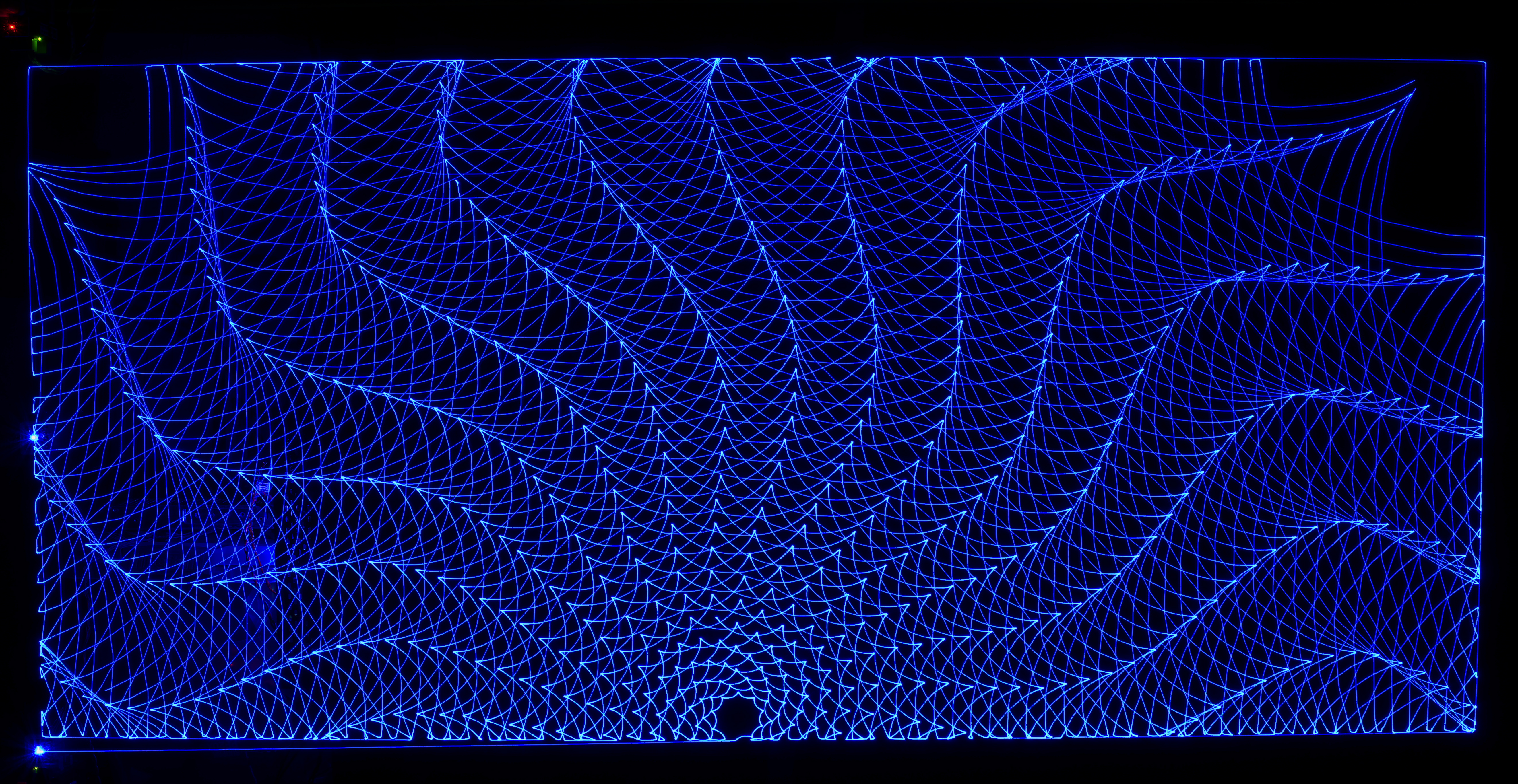
It took about 5 minutes with the speed at 2000, accel at 10k, and jerk at 12000.
This may be of interest to those who still use endstop switches to set Z=0 in their printer. I was using a lever/cam with a clicky microswitch to set the Z=0 position in my printer, but it developed a problem so I decided to work on a replacement. I changed to an opto endstop that has an LED that lights when the beam is broken. But that's not the interesting part. I made a differential screw driven adjuster for the flag that breaks the light beam. The differential screw moves the flag 100 um per rev so it is very easy to make small adjustments without over adjusting. The differential screw assembly mounts on the bed support that moves up and down and the opto endstop mounts of the printer's frame:

The screw was made by turning the end of an M5x0.8 screw down to 4 mm on a lathe and then threading it for M4x0.7. When you turn the screw 1 rev, it moves 0.8 mm up, while the M4 nut (and the flag) move up 0.1 mm. It has about 2mm of adjustment range, so you get it close by moving the opto endstop on the frame, and make fine adjustment with the screw.
More: https://drmrehorst.blogspot.com/2020/03/a-new-z-axis-optical-endstop-design-for.html
@o_lampe Here's my PERL script for dual speed operation. I used a LOT of notes to make it easy for me to modify or fix because I don't do a lot of programming and have to relearn it for each project.
This is how it is invoked:
E:\Downloads>perl -w dual_speedify_v2.pl

Warning- there's no error trapping, so be careful when you answer
the questions that will follow. Use at your own risk!

Type the name of the sandify pattern file:
250519_01.gcode
Enter the drawing speed in mm/sec
150
Enter the edge speed in mm/sec
1000
Enter the minimum X value of the pattern.
0
Enter the maximum X value of the pattern.
590
Enter the minimum Y value of the pattern.
0
Enter the maximum Y value of the pattern.
980
Enter the home position X ordinate.
590
Enter the home position Y ordinate.
0

Processing is complete.

The dual speed output file is called 250519_01_9000_60000.gcode

Check the output file to make sure it does what you think it will.
And the attached file is the result. 250519_01_9000_60000.gcode ]
@o_lampe What do you plan to use to generate the drawing and erase pattern files? Maybe the keepout areas can be defined there.
You can do all sorts of stuff with post processors. I use a PERL post processor to set the speed of moves on my table. It steps through the pattern file and determines whether each line of gcode draws on the table or moves the ball along the edges. If it's edge motion, it executes it at high speed (usually 1000 mm/sec), and if it's drawing on the table it executes at a lower speed (to preserve detail in the drawing).
@dc42 I have drawing files in /gcodes/draw/ and wipe files in /gcodes/wipe/ folders. All files are renamed with numeric names and gcode extension, like "16.gcode".
I have tried about 50 variations on:
M98 P{/gcodes/draw/random(214)^".gcode"}
and get various error messages, mostly about expecting a string at one column or another.
How do I specify the folder to find the target files? Is this syntax documented somewhere?
Thanks!
m98 P"/gcodes/draw/^{random(22)}^.gcode"
Warning: Macro file /gcodes/draw/^{random(22)}^.gcode not found
ok
M98 P"/gcodes/draw/{random(55)^".gcode"}
Warning: Macro file /gcodes/draw/{random(55)^ not found
Error: Bad command: gcode"}
ok
M98 P{/gcodes/draw/{andom(55)^".gcode"}
Error:  at column 7: M98: expected an expression
ok
M98 P{/gcodes/draw/{random(55)^".gcode"}
Error:  at column 7: M98: expected an expression
ok
M98 P{/gcodes/draw/random(55)^".gcode"}
Error:  at column 7: M98: expected an expression
ok
M98 P "/gcodes/draw/{random(55)^".gcode"}
Error:  at column 6: M98: expected a string expression
Error: Bad command: gcode"}
ok
M98 P "/gcodes/draw/{random(55)^.gcode"}
Error:  at column 6: M98: expected a string expression
ok
M98 P {/gcodes/draw/random(55)^.gcode"}
Error:  at column 6: M98: expected a string expression
ok
M98 P{random(55)^".gcode"}
Warning: Macro file 39.gcode not found
ok
M98 P /gcodes/draw/{random(55)^".gcode"}
Error:  at column 6: M98: expected a string expression
Error: Bad command: gcodes/draw/{random(55)^".gcode"}
ok
M98 P "/gcodes/draw/{random(55)^".gcode"}"
Error:  at column 6: M98: expected a string expression
Error: Bad command: gcode"}"
ok
M98 P "/gcodes/draw/{random(55)^".gcode"
Error:  at column 6: M98: expected a string expression
Error: Bad command: gcode"
ok
M98 P "/gcodes/draw/{random(55)^".gcode"}
Error:  at column 6: M98: expected a string expression
Error: Bad command: gcode"}
ok
M98 P /gcodes/draw/{random(55)^".gcode"}
Error:  at column 6: M98: expected a string expression
Error: Bad command: gcodes/draw/{random(55)^".gcode"}
ok
M98 P "/gcodes/draw/{random(55)^".gcode"}"
Error:  at column 6: M98: expected a string expression
Error: Bad command: gcode"}"
ok
M98 P "/gcodes/draw/"^{random(55)^".gcode"}"
Error:  at column 6: M98: expected a string expression
ok
M98 P /gcodes/draw/^{random(55)^".gcode"}
Error:  at column 6: M98: expected a string expression
Error: Bad command: gcodes/draw/^{random(55)^".gcode"}
ok
M98 P {/gcodes/draw/random(55)^".gcode"}
Error:  at column 6: M98: expected a string expression
ok
M98 P {0:/gcodes/draw/random(55)^".gcode"}
Error:  at column 6: M98: expected a string expression
ok
M98 P "0:/gcodes/draw/"^{random(55)^".gcode"}
Error:  at column 6: M98: expected a string expression
ok
M98 P "0:/gcodes/draw/"{random(55)^".gcode"}
Error:  at column 6: M98: expected a string expression
ok
M98 P"0:/gcodes/draw/"{random(55)^".gcode"}
Warning: Macro file 0:/gcodes/draw/ not found
ok
M98 P{0:/gcodes/draw/random(55)^".gcode"}
Error:  at column 8: M98: expected '}'
ok
M98 P"{0:/gcodes/draw/random(55)"^".gcode"}
Warning: Macro file {0:/gcodes/draw/random(55) not found
ok
M98 P"0:/gcodes/draw/{random(55)"^".gcode"}
Warning: Macro file 0:/gcodes/draw/{random(55) not found
ok
M98 P"0:/gcodes/draw/{random(55)}"^".gcode"}
Warning: Macro file 0:/gcodes/draw/{random(55)} not found
ok
M98 P"0:/gcodes/draw/{random(55)}"^".gcode"
Warning: Macro file 0:/gcodes/draw/{random(55)} not found
ok
M98 P"0:/gcodes/draw/"{random(55)}"^".gcode"
Warning: Macro file 0:/gcodes/draw/ not found
Error: Bad command: gcode"
ok
M98 P"0:/gcodes/draw/"^{random(55)}"^".gcode"
Warning: Macro file 0:/gcodes/draw/ not found
Error: Bad command: gcode"
ok
M98 P"0:/gcodes/draw/"^{random(55)}^".gcode"
Warning: Macro file 0:/gcodes/draw/ not found
ok
M98 P"0:/gcodes/draw/"^{random(55)^".gcode"}
Warning: Macro file 0:/gcodes/draw/ not found
ok
M98 P"0:/gcodes/draw/"^"{random(55)^".gcode"}
Warning: Macro file 0:/gcodes/draw/ not found
Error: Bad command: gcode"}
ok
M98 P"0:/gcodes/draw/^"{random(55)^".gcode"}
Warning: Macro file 0:/gcodes/draw/^ not found
ok
@o_lampe Thanks. All the files are tested, so not an issue. I'll be able to access the machine this afternoon and will try out the random selection. I'm not too sure about the syntax. I've been testing the syntax via the console on my 3D printer and it doesn't look promising. If I enter M98 p"{random(55)}^.gcode" it returns {random(55)}^.gcode not found. It isn't converting the expression to a random number, or even treating it as an expression, just a string of characters. I've tried a few variations on the syntax and none have worked so far.
When I run echo random(416) on the console, it returns a random number (sometimes 3 digits), so I know random is working the way it should. Maybe I need to set a variable to a random value, and use that variable in the M98 command.
Renaming the files is pretty easy- I used Bulk Rename Utility. It takes just a couple seconds to set it up.
@dc42 I'm having some trouble figuring out how to randomly select a file from the /gcodes/ folder. Do I have to put the files names in that folder in an array, or is there a way to declare the contents of the /gcodes/ folder as an array? I currently have about 200 gcode files stored in the /gcodes/ folder, and I add more files to it as I generate them.
I typically run a macro at the end of the config.g file, like this:
M98 P"/macros/macro01"
And that macro file looks like this (though much longer):
; file name: macro01
M98 P"/gcodes/wipe_03.gcode"
M98 P"/gcodes/file_04.gcode"
G04 S60
M98 P"/gcodes/wipe_01.gcode"
M98 P"/gcodes/file_02.gcode"
G04 S60
M98 P"/gcodes/wipe_02.gcode"
M98 P"/gcodes/file_06.gcode"
.
.
.
Should macro01 file look like this:
; file name: macro01
var myfile = {"file_01", "file_02", "file_03", "file_04", "file_05", "file_06"}
M98 P"/gcodes/^myfile[random 6]^.gcode"
G04 S60
M98 P"/gcodes/^myfile[random 6]^.gcode"
.
.
.
It seems like I'll quickly run out of line length if I try to put all 200 file names in the variable declaration.
Another idea- rename all the files in the gcodes folder with simple numeric names:
1.gcode, 2.gcode.... 212.gcode
Then in the macro file, select a random pattern file like this:
M98 P"/gcodes/^{random(212)}^.gcode"
Sorry if this stuff is too basic. I've been away from programming for a looooong time.
@dc42 Thanks! I will try it out and see if I can get it working.
@dc42 Will it work with the Duet2 Wifi board? I typically set up the controller to run a macro containing a sequence of patterns to run at power up. That way I don't need to have a UI or even to connect to the machine.
I am not familiar with the way tick counter works. If I use the random function to select files to run instead of a macro that contains a specific sequence, will it give me the same sequence each time I power up the board, or is there some variability in the power up timing that will result in a different seed when I use the random function after each power up? Thanks!
@o_lampe I don't know that you gain much drawing area using a delta mechanism. I don't think you can draw any further than the towers, so you'll still have a wide, undrawn perimeter like what you get with a corexy or other rectangular mechanism. A lot of people make SCARA mechanism sand tables. With those the magnet is on the end of an arm that can reach very close to the edges of the table. The mechanism is located at the center of the table, so there's plenty of room for people's legs/feet if they are sitting around the table.
@dc42 The controller has no RTC, so what seeds the random function? If I set up a macro to randomly select and run gcode files from a list, will it give me a different file/sequence each time the controller is powered up, or will it give me the same pseudo random sequence of files each time? Thanks!