Duet WiFi Expansion Board. PMW Control of 80W Laser Module
-
I've heard very good feedbacks about this laser module and eventually decided to give it a try .
AliExpress 80w LAserIn Duet wiki is saying -
Note: if your system includes either a DueX expansion board or an expansion Breakout Board, then that board already includes this circuitry.So I'm attaching the +12v and ground of the laser to Duet 12v power supply
And PWM to PWM7 on Expansion board .
When the machine is Laser Mode (m452)- the laser is ON from the start. if I unplug the PWM - it's doesn't work.
If the ground cable is also connected to Expansion PWM7 ground - nothing happening...
; Configuration file for Duet WiFi (firmware version 3.3) ; General preferences G90 ; send absolute coordinates... M83 ; ...but relative extruder moves M550 P"M1" ; set printer name M669 ;K1 ;Set Cartesian mode ;M453 ; CNC Mode M452 C"exp.heater7" F250 ; Enable Laser mode, on exp.heater7, with max intensity being 255, and a PWM frequency of 200 ; Network M551 P"*****" ; set password M552 S1 ; enable network M586 P0 S1 ; enable HTTP M586 P1 S0 ; disable FTP M586 P2 S0 ; disable Telnet ; Drives M569 P0 S0 ; physical drive 0 goes forwards M569 P1 S1 ; physical drive 1 goes forwards M569 P2 S1 ; physical drive 2 goes forwards M569 P3 S1 ; physical drive 3 goes forwards M569 P4 R-1 ; physical drive 4 goes forwards ;------------------Y MOTOR------------------------------------------------------------- M569 P6 R1 T2.5:2.5:5:5 S1 M569 P7 R1 T2.5:2.5:5:5 S1 ; driver 6,7 direction is backwards and requires an active high enable, 5us minimum step pulse, 2.5us minimum step interval, 5us DIR setup, and 7.5us hold time ;-----------------Z MOTOR-------------------------------------------------------------- M569 P5 R1 T2.5:2.5:5:5 S1 ; driver 5 direction is backwards and requires an active high enable, 5us minimum step pulse, 2.5us minimum step interval, 5us DIR setup, and 7.5us hold time ;-----------------EXTRUDER 0 MOTOR----------------------------------------------------- ;M569 P9 S0 R1 T5:2.5:5:7.5 ; driver 9 direction is backwards and requires an active high enable, 5us minimum step pulse, 2.5us minimum step interval, 5us DIR setup, and 7.5us hold time M584 X0 Y6:7 Z5 U1 E3 ; set drive mapping to external drivers M350 X128 U128 M92 X640.00 Y171.00 Z5050.00 U640 E400.00 ;M92 X80.00 Y171.00 Z5050.00 U80 E400.00 ; set steps per mm M566 X2000.00 Y1300.00 U4000 Z60.00 E800.00 ; set maximum instantaneous speed changes (mm/min) M203 X4000.00 Y4000.00 U21000 Z300.00 E1000.00 ; set maximum speeds (mm/min) M201 X600.00 Y600.00 U4500 Z80.00 E900 ; set accelerations (mm/s^2) M906 X1000 Y1200 Z600 U1200 E760 ; set motor currents (mA) and motor idle factor in per cent M84 S30 ; Set idle timeout ; Axis Limits M208 X0 Y0 U0 Z-30 S1 ; set axis minima M208 X1019.5 Y790 U800 Z550 S0 ; set axis maxima ; Endstops M574 X2 S1 P"!xstop" ; configure switch-type (e.g. microswitch) endstop for high end on X via pin xstop M574 Y1 S1 P"!ystop" ; configure switch-type (e.g. microswitch) endstop for low end on Y via pin ystop M574 Z1 S1 P"!zstop" ; configure switch-type (e.g. microswitch) endstop for low end on Z via pin zstop M574 U1 S1 P"!e1stop" ; configure switch-type (e.g. microswitch) endstop for low end on U via pin zstop ; Z-Probe M558 P0 H5 F120 T6000 ; disable Z probe but set dive height, probe speed and travel speed M557 X15:990 Y45:700 S60 ; define mesh grid ; Heaters M308 S1 P"e0temp" Y"thermistor" T100000 B4138 M950 H1 C"e0heat" T1 ; create nozzle heater output on e0heat and map it to sensor 1 M307 H1 B0 S1.00 ; disable bang-bang mode for heater and set PWM limit M143 H1 S280 ; set temperature limit for heater 1 to 280C ; Fans M950 F0 C"fan0" Q100 ; create fan 0 on pin fan0 and set its frequency M106 P0 S1 R1 L15 H-1 ; set fan 0 value. Thermostatic control is turned off M950 F1 C"Fan1" Q3300 ; create fan 1 on pin fan1 and set its frequency M106 P1 S1 L1 X1 B0.1 H1 T45 ; set fan 1 value. Thermostatic control is turned on M950 F2 C"fan2" Q500 ; create fan 0 on pin fan0 and set its frequency M106 P2 S1 R1 L255 H1 ; Tools ''' Create a tool that uses the low end (X) carriage''' ;;M563 P0 S"Spindle" F0 ;R0 ; define tool 0 G10 P0 X0 Y0 Z0 S0 R0 ; set tool 0 axis offsets ; Configure Tool 0 as the CNC Spindle M950 R0 C"e1heat" Q2000 L0:12000 ; Create spindle index 0 with ; inverted PWM output on E0 heater pin ; and spindle speed of 12000 rpm at maximum PWM M563 P0 R0 S"Spindle" ; Create Tool 0 with Spindle 0 and call it Spindle G10 P0 X0 Y0 Z0 S0 R0 ; Set Tool 0 axis offsets M568 P0 F0 ; Set Tool 0 to default RPM of 0 T0 ; Select Tool 0 ''' Create a tool that uses the high end (U) carriage''' M563 P1 S"Extruder" D0 H1 X3 F2 ; define tool 0 ;G10 P1 Y-7.4 U-33.5 Z-17 G10 P1 Y7.5 Z-17 ; set tool 0 axis offsets G10 P1 R0 S0 ; set initial tool 0 active and standby temperatures to 0C ; Custom settings are not defined M575 P1 B57600 S1 - the laser is ON from the start. if I unplug the PWM - it's doesn't work.
-
@allsirius don't use "exp.heater7" in that command, use "duex.pwm5". Pin "exp.heater7" refers to the signal on the expansion bus, which is inverted because it is active low.
Duet WiFi hardware designer and firmware engineer
Please do not ask me for Duet support via PM or email, use the forum
http://www.escher3d.com, https://miscsolutions.wordpress.com -
@dc42 Thank you for quick replay !
I guess I wasn't clear enough about my hardware setup:
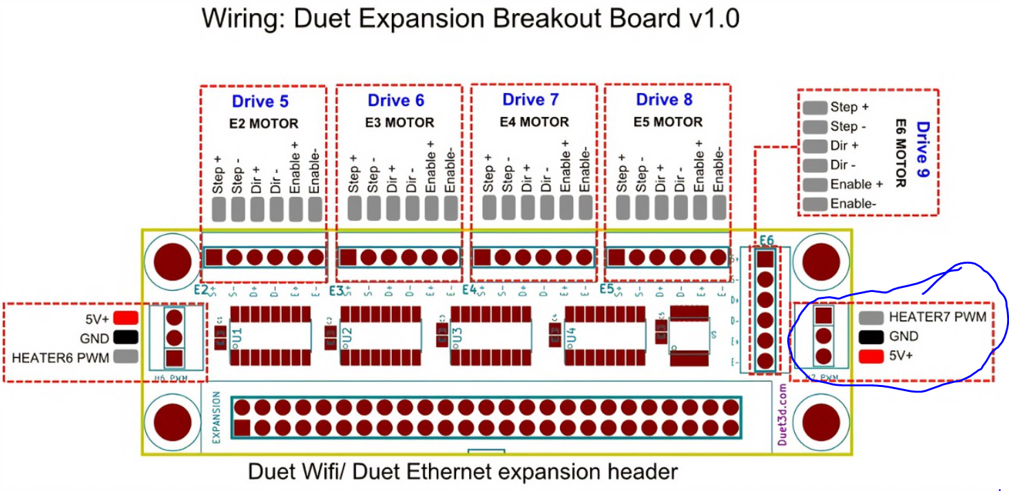
I'm using this port on Duet Expansion Breakout Board
And after I used M452 C"duex.pwm5" F250 command in my Config.g the laser is acting the same. Full power from the start and the fans on it are always on from the V+ and ground form my power supply , even I'm unplugging the PWM from the board.
So I think I'll need to power it from the third free Fan port on my Duet WiFi to avoid the spinning the Laser fans while it's not in work. -
@allsirius do not try to power the laser from a fan or heater port. If you that then you will probably damage the laser control module, the Duet port that it is connected to, or both.
Please provide a link to the documentation for that laser.
If you have a multimeter, please try removing the M452 line from config.g and disconnect the laser, then start the Duet and measure the voltage between the PWM output and ground. It should be 0V.
Duet WiFi hardware designer and firmware engineer
Please do not ask me for Duet support via PM or email, use the forum
http://www.escher3d.com, https://miscsolutions.wordpress.com -
@dc42 Here is all what I've got about the laser ..
Laser Aliexpress link..... -
@allsirius I'm using more or less the same laser module, probably just another form factor: LaserTree LT-80W-LE-Mini
I first used it with this circuit: https://photos.app.goo.gl/i8Mxxm5eNJhgfwycA
But now I have switched to the one from the wiki.
What is missing in the wiki is the info that this circuit needs a inverted signal.
And according to the wiki page about the breakout board, this is true there as well.
The example to control a servo is: M950 S0 C"!exp.heater7"
So, you probably have to use it like this: M452 C"!exp.heater7" F250And to control the fan you have to cut the +12V supply to the module.
As dc42 said, you can't use heater and fan outputs. If i recall correctly, they switch the negative side (GND).
So you probably would need a separate relay or so to do this.