Indipendent z axis + probe levelling
-
I have a 4 z motors core xy in the making. I configured it to level with the probe and it works fine, but i'm not satisfied with the precision because of steps lost when turning on and moving the motors for the first time. I then added 4 endstops and looking at https://duet3d.dozuki.com/Guide/Independent+Z+motors+and+endstop+switches+in+RRF2/18 and i tried to modify my config.g, homeall.g and homez.g accordingly.
I'm running a duet 2 wifi + duex 5 with firmware 3.3.
when i start the printer i get the following errors:
error: in file macro line 33 column : array too long, max lenght=0 (can't read this one in time it doesn't stay in the paneldue screen for enough time)
error: in file macro line 37 column 58: M206: array too long, max lenght=0
error: in file macro line 38 column 44: M906: array too long, max lenght=0
Error: bad drive number
Error: Tool 0 not found
Error: Tool 0 not foundI also noticed thet sending m119 returns:
Endstops - X: not stopped, Y: not stopped, Z: not stopped, U: at min stop, V: at min stop, W: at min stop, A: at min stop, Z probe: not stopped
u v w a are always at min stop even if wired like the others, and even if pressed while sending m119
from the errors i guess it's about the declaration of axis values, i only found that guide and i'm struggling to find a solution, any help is apreciated. Thank you
Here there are the files:Config.g
; Configuration file for Duet WiFi (firmware version 3.3)
; executed by the firmware on start-up
;
; generated by RepRapFirmware Configuration Tool v3.3.4 on Tue Oct 19 2021 11:13:27 GMT+0200 (Ora legale dell’Europa centrale)

; General preferences
M575 P1 S1 B57600                                  ; enable support for PanelDue
G90                                                ; send absolute coordinates...
M83                                                ; ...but relative extruder moves
M550 P"Da Queen"                                   ; set printer name
M669 K1                                            ; select CoreXY mode

; Network
M552 S1                                            ; enable network
M586 P0 S1                                         ; enable HTTP
M586 P1 S0                                         ; disable FTP
M586 P2 S0                                         ; disable Telnet

; Drives
M569 P0 S0                                         ; physical drive 0 goes backwards
M569 P1 S0                                         ; physical drive 1 goes backwards
M569 P2 S1                                         ; physical drive 2 goes forwards
M569 P3 S1                                         ; physical drive 3 goes forwards
M569 P5 S0                                         ; duex5 motor z1  goes backwards
M569 P6 S0                                         ; duex5 motor z2 goes backwards
M569 P7 S0                                         ; duex5 motor z3 goes backwards
M569 P8 S0                                         ; duex5 motor z4 goes backwards


M584 X0 Y1 Z5:6:7:8 U5 V6 W7 A8 P3                 ; nomino Z5 Z6 Z7 Z8 anche come U5 V6 W7 A8


M350 X16 Y16 Z16 U16 V16 W16 A16 E16 I1                                                       ; configure microstepping with interpolation
M92 X80.00 Y80.00 Z400.00 U400.00 V400.00 W400.00 A400.00 E420.00                             ; set steps per mm
M566 X900.00 Y900.00 Z60.00 U60.00 V60.00 W60.00 A60.00 E120.00                               ; set maximum instantaneous speed changes (mm/min)
M203 X6000.00 Y6000.00 Z180.00 U180.00 V180.00 W180.00 A180.00 E1200.00                       ; set maximum speeds (mm/min)
M201 X500.00 Y500.00 Z20.00 U20.00 V20.00 W20.00 A20.00 E250.00                               ; set accelerations (mm/s^2)
M906 X1000 Y1000 Z900 U900 V900 W900 A900 E1000 I30                                           ; set motor currents (mA) and motor idle factor in per cent
M84 S30                                                                                       ; Set idle timeout


; Axis Limits
M208 X0 Y0 Z0 U0 V0 A0 W0 S1                                                                  ; set axis minima
M208 X490 Y640 Z415 U415 V415 W415 A415 S0                                                    ; set axis maxima

M307 H7 A-1 C-1 D-1                                ;disable heater 7 to free pwm 5

; Endstops
M574 X1 S1 P"!xstop"                               ; configure switch-type (e.g. microswitch) endstop for low end on X via pin xstop
M574 Y1 S1 P"!ystop+!e0stop"                       ; configure switch-type (e.g. microswitch) endstop for low end on Y via pin ystop
M574 Z1 S2                                         ; configure Z-probe endstop for low end on Z
M574 U1 S1 P"!exp.e2stop"                          ; configure ine endstop for each axis: U V W A
M574 V1 S1 P"!exp.e3stop"
M574 W1 S1 P"!exp.e4stop"
M574 A1 S1 P"!exp.e5stop"

; Z-Probe
M950 S0 C"duex.pwm5"                               ; create servo pin 0 for BLTouch
M558 P9 C"^zprobe.in" H5 F120 T6000                ; set Z probe type to bltouch and the dive height + speeds     M558 P9 C"^zprobe.in" H5 F120 T6000
G31  P500 X0 Y0 Z0.4                               ; set Z probe trigger value, offset and trigger height
M557 X15:215 Y15:195 S20                           ; define mesh grid

; Heaters
M308 S0 P"e0temp" Y"thermistor" T100000 B4138     ; configure sensor 0 as thermistor on pin e0temp
M950 H1 C"e0heat" T0                              ; create nozzle heater output on e0heat and map it to sensor 1
M307 H1 B0 S1.00                                  ; disable bang-bang mode for heater  and set PWM limit
M143 H1 S350                                      ; set temperature limit for heater 1 to 280C

; Fans
M950 F0 C"fan0" Q500                           ; create fan 0 on pin fan0 and set its frequency
M106 P0 S0 H-1                                 ; set fan 0 value. Thermostatic control is turned off
M950 F1 C"duex.fan5" Q500                      ; create fan 1 on pin DUEX FAN8 and set its frequency
M106 P1 S1 H1 T45                              ; set fan 1 value. Thermostatic control is turned on

; Tools
M563 P0 D0 H1 F0                               ; define tool 0
G10 P0 X0 Y0 Z0                                ; set tool 0 axis offsets
G10 P0 R0 S0                                   ; set initial tool 0 active and standby temperatures to 0C
; Custom settings are not defined

; Miscellaneous
M911 S10 R11 P"M913 X0 Y0 G91 M83 G1 Z3 E-5 F1000" ; set voltage thresholds and actions to run on power loss
Homeall.g
; homeall.g
; called to home all axes
;
; generated by RepRapFirmware Configuration Tool v3.3.4 on Tue Oct 19 2021 11:13:27 GMT+0200 (Ora legale dell’Europa centrale)
G91                     ; relative positioning
G1 H2 Z5 F6000          ; lift Z relative to current position
G1 H1 X-495 Y-645 F1800 ; move quickly to X or Y endstop and stop there (first pass)
G1 H1 X-495             ; home X axis
G1 H1 Y-645             ; home Y axis
G1 X5 Y5 F6000          ; go back a few mm
G1 H1 X-495 F360        ; move slowly to X axis endstop once more (second pass)
G1 H1 Y-645             ; then move slowly to Y axis endstop
G90                     ; absolute positioning

M98 Phomez.g
Homez.g
; homez.g ; called to home the Z axis ; ; generated by RepRapFirmware Configuration Tool v3.3.4 on Tue Oct 19 2021 11:13:27 GMT+0200 (Ora legale dell’Europa centrale) G91 ; relative positioning G1 H2 Z5 F6000 ; lift Z relative to current position ; split Z motor control to Z and U and V and W and A ; for it to work we have to show U (param P6) in the UI M584 U5 V6 W7 A8 P6 ; Move Z and U and V and W and A down until the switches triggers G1 S1 U-420 V-420 W-420 A-420 F1000 ; back to combined axes and hidden U V W A M584 Z5:6:7:8 P3 G90 ; absolute positioning G1 X15 Y15 F6000 ; go to first probe point G30 ; home Z by probing the bed ; Uncomment the following lines to lift Z after probing ;G91 ; relative positioning ;G1 Z5 F100 ; lift Z relative to current position ;G90 ; absolute positioning -
Why do you have the axes U, V, A and W?
If you want to just use the 4 independent Z endstops for homing Z you don't need them.
Your answer determines where I will go from here.
Thanks.
Frederick
Printers: a small Utilmaker style, a small CoreXY and a E3D MS/TC setup. Various hotends. Using Duet 3 hardware running 3.4.6
-
Ok so i just have to home z normally? I'd like to "pair" every z motor with a stepper, so if for example z3 is the only one not homed it will be the only one moving, in order to have them all parallel. After that i'll use the probe to home again in order to absorb all the plane imperfections. From what i've understood u have to split z axis in order to achieve that, did i get all wrong?
-
@fcwilt Ok i actually found in the gcode dictionary https://duet3d.dozuki.com/Wiki/M574 at the end it says:
" New parameter P gives the pin name(s) for the endstop(s) for the specified axis. If the number of pins matches the number of motors assigned to that axis, motors will be stopped individually when their endstop switches trigger.
To use two Z motors using independent homing switches, declare two Z motors in M584, then declare two pins for Z endstops in a single M574 command. Example
M584 X0 Y1 Z2:3 E4
M574 Z1 S1 P"io2.in+io3.in" ; Z axis with two motors, individual min endstops, active high
The order of endstop switch pin names in M574 must match the order of Z motor driver numbers in M584. When homing Z, RRF3 homes the motors of the axis at the same time, independently to their defined endstops. "the problem is that i connected my motors to a duex5
M569 P0 S0                                         ; physical drive 0 goes backwards
M569 P1 S0                                         ; physical drive 1 goes backwards
M569 P2 S1                                         ; physical drive 2 goes forwards
M569 P3 S1                                         ; physical drive 3 goes forwards
M569 P5 S0                                         ; duex5 motor z1  goes backwards
M569 P6 S0                                         ; duex5 motor z2 goes backwards
M569 P7 S0                                         ; duex5 motor z3 goes backwards
M569 P8 S0                                         ; duex5 motor z4 goes backwards


M584 X0 Y1 Z5:6:7:8 E3                             ; configure drives


; Endstops
M574 X1 S1 P"!xstop"                               ; configure switch-type (e.g. microswitch) endstop for low end on X via pin xstop
M574 Y1 S1 P"!ystop+!e0stop"                       ; configure switch-type (e.g. microswitch) endstop for low end on Y via pin ystop
M574 Z1 S2                                         ; configure Z-probe endstop for low end on Z
M574 Z1 S1 P"!exp.e2stop"                           ; configure endstop for Z axis
M574 Z1 S1 P"!exp.e3stop"
M574 Z1 S1 P"!exp.e4stop"
M574 Z1 S1 P"!exp.e5stop"
it seems to not pair them even if physical drive 5,6,7,8 are actually e2,e3,e4,e5 motors.
Endstops light on when pressed but with m119 they always remain triggered/not triggered based on how i define themthank you
Marco
-
M574 Z1 S1 P"!exp.e2stop+!exp.e3stop+!exp.e4stop+!exp.e5stop"To my understanding it should look like this
-
i tried like that and nothing changes, i even decommented/ removed all bltouch lines just to try to use the endstops alone but it doesn't work...
This is the code now; Drives M584 X0 Y1 Z5:6:7:8 E3 ; drive mapping M569 P0 S0 ; physical drive 0 goes backwards M569 P1 S0 ; physical drive 1 goes backwards M569 P2 S1 ; physical drive 2 goes forwards M569 P3 S1 ; physical drive 3 goes forwards M569 P5 S0 ; duex5 motor z1 goes backwards M569 P6 S0 ; duex5 motor z2 goes backwards M569 P7 S0 ; duex5 motor z3 goes backwards M569 P8 S0 ; duex5 motor z4 goes backwards ; Endstops M574 X1 S1 P"!xstop" ; configure switch-type (e.g. microswitch) endstop for low end on X via pin xstop M574 Y1 S1 P"!ystop+!e0stop" ; configure switch-type (e.g. microswitch) endstop for low end on Y via pin ystop M574 Z1 S1 P"exp.e2stop+exp.e3stop+exp.e4stop+exp.e5stop" ; configure endstop for Z axis -
Are the pin names you used for your M574 Z command the pins your Z endstops are connected to?
If the endstops are connected to the duex5 board I believe you need to use the duex prefix, not the exp prefix.
Have you checked the status of each Z endstop in the Object Model viewer to verify the correct states of each endstop when activated/not activated?
Frederick
-
i tried with duex. before as well, i checked on the board and the pins are correct.
I solved this problem, i had the endstop jumper set to 3.3v instead of 5v...
But i have a new one now:
logic is inverted and i can't get it the other wayM574 X1 S1 P"!xstop" ; configure switch-type (e.g. microswitch) endstop for low end on X via pin xstop M574 Y1 S1 P"!ystop+!e0stop" ; configure switch-type (e.g. microswitch) endstop for low end on Y via pin ystop M574 Z1 S1 P"duex.e2stop+duex.e3stop+duex.e4stop+duex.e5stop"i tried both :
M574 Z1 S0 P"duex.e2stop+duex.e3stop+duex.e4stop+duex.e5stop"
M574 Z1 S1 P"!duex.e2stop+!duex.e3stop+!duex.e4stop+!duex.e5stop"The result with m119 is now no z endstop, i mean it's the exact same code used for x and y endstops and it works there...
I'm not familiar with object model viewer , how can I use it?
Thnank you for your patience -
@marcocha said in Indipendent z axis + probe levelling:
i tried both :
M574 Z1 S0 P"duex.e2stop+duex.e3stop+duex.e4stop+duex.e5stop"
M574 Z1 S1 P"!duex.e2stop+!duex.e3stop+!duex.e4stop+!duex.e5stop"S0 is not a valid value for the S parameter.
The second is correct is inversion is needed.
Frederick
-
Here is the location in the DWC where you can verify if the Object Model viewer is running and, if not, start it running.
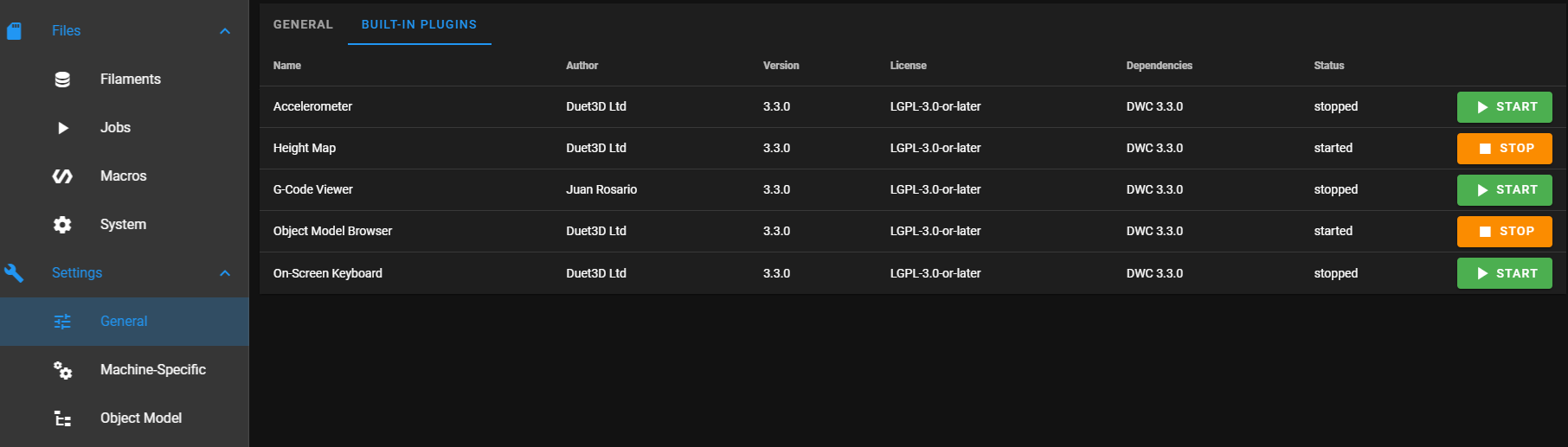
-
ok i started it, since i don't know what exactly to look for i found the endstop section that corresponds to m119
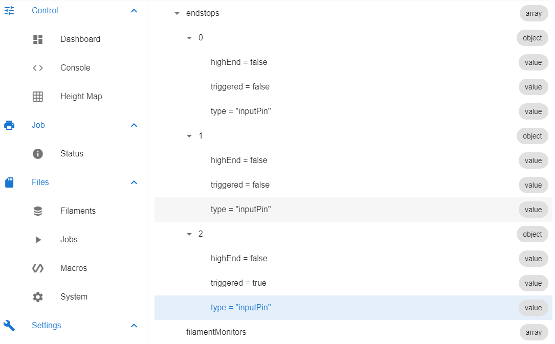
It says triggered = true when they were not pressed so the logic is the opposite, the problem is that if i declare them with ! i get an error
Error in file macro line 49 (that one) m574 string too long -
Yes - there was a problem with lines being too long at one time but I thought it was fixed in firmware 3.3.
Could you move one or two of the endstops to the E0 and E1 inputs on the Duet board? That should solve the problem with line length.
Frederick
-
@fcwilt i can, i will move one motor to z on the duet and the relative endstop too, so it should still mantain the order. Hope in a fix soon so i can just use everything on the duet
thank you
Marco
-
Glad to hear it.
Just FYI there is no requirement that you move the stepper motor connection.
Frederick