Trying to diagnose a board problem with thermistors
-
For the Duet2 pcb 1.04c
Okay so here's the problem.
None of the thermistor connectors work accept the one for measuring the bed temperature.
It was a difficult problem for me to diagnose because at first I thought that the problem was with the actual thermistors I tried.What is happening is that the voltage starts off at 3.3V on the open pins. But it immediately starts to drop and will settle down to about 0.15 volts over a period of 5mins or so.
The pins for thermistor0 read at 3.3Volts.
All the others including the expansion pins have the voltage drop problem.
I've downloaded the pcb file to look at the board using KiCad but I can't figure out where the problem might be.
What I noticed was that thermistor0 is getting voltage from ADVREF but the other thermistors don't seem to have that in their connections.So I'm not sure where to go with this.
I think it might be a bad capacitor but that's just a half educated guess. Just because of the way the voltage does the slow drain.So I want to know is problem happened before?
Is there a single point on the board where there might be a chip that's gone bad?
Or is it actually at the Atmel CPU?
How can I narrow down the area where the problem might be?
I've noticed a fuse (F1) in the schematics but I'm not so sure that's the problem because one thermistor works.
I do not have hands steady enough to measure individual pins coming out of the Atmel but from the way a thermistor circuit is supposed to be designed I seriously think the source voltage is the problem anyway.As for my knowledge I learned circuit and board design back in college (25 years ago) but I could only design the most basic of boards right now.
Anyone have an ideas be much appreciated.
ThanksDaniel
-
@dan-degagne said in Trying to diagnose a board problem with thermistors:
Okay so here's the problem.
None of the thermistor connectors work accept the one for measuring the bed temperature.Let's back up a bit. What is the actual problem?
What thermistors do you have?
Where do you have them connected?
How do you have them configured?
What behavior are you actually seeing? -273c? 2000c?Please post the results of M122 and M98 P"config.g".
Also post your full config.g -
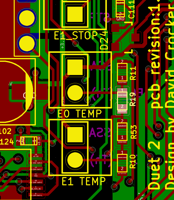
@dan-degagne it sounds to me that the thermistor series resistors have failed. They are R19 and R53 close to the E0_TEMP and E1_TEMP connectors respectively. Alternatively, the trace that feeds them with ADVREF may have broken.
I suggest you test whether R19 and R53 3.3V on the ADVREF sides. This PCB snippet is for 1.04b but I don't think it changed in 1.04c.
Duet WiFi hardware designer and firmware engineer
Please do not ask me for Duet support via PM or email, use the forum
http://www.escher3d.com, https://miscsolutions.wordpress.com -
@dc42 Thanks for your help, David. Okay, I measured R19 and R53. They both give me 4.7K and from reading the resistors that is correct.
I also checked out the resistors for the thermisters3-7 and they all show 10K which checks out.So I checked the traces for ADVREF and found the problem. I found a ~4M ohm resistance on the trace which explains a lot of the behaviour I've been observing. Would explain why I was still getting a 3.3V that dropped down to 0.15Volts as I measured it.
I have not yet pinpointed the bad trace though. I've stared at the board till my eyes bleed and I spotted no burn marks or scratches that would indicate the area. Just that it's fine up until the expansion header pin. From there I see goes to the bed thermistor resistor. Which is also fine.
So any suggestions where I could try to run a wire to skip over the bad trace?
No way I can solder to a side of any of those resistors. I don't have a scope, steady hand, and the skills to do something like that.I was thinking I could start it on the back at the ADVREF pin on the expansion header and then solder to something big enough to try to see if that would jump the bad spot and get my board finally working.
Thanks